45 / 64
613, 618
11.2 Operation and adjustments
DANGER
Electric shock by dangerous voltage!
Adjustments are made with the actuator
cover removed and while the unit is
connected to the power supply. Electric
shock can cause severe burns and fatal
injury. Therefore, refer all adjustments
to qualifi ed electricians.
The GEMÜ 613 / 618 motorized valves
are supplied in the "OPEN" position. No
additional parts are required before installing
the unit directly into the system.
For the use of integrated control
modules, parameters can be modified or
set according to the specific system:
Control module E1:
Position control via integrated three-point
controller by means of external set value
0-10 V (plus code 6025 / 6026 - see order
data)
Control module E2:
Position control via integrated three-point
controller by means of external set value
0/4-20mA (plus code 6025 / 6026 - see
order data)
Control module E3:
Process control via integrated controller
by means of external set value 0/4-20 mA
external actual value defi nition 0/4-20 mA
(plus code 6023 / 6024 - see order data)
Adjustable parameters:
Position of the valve at set value
0 V or 0 / 4 mA
Position of the valve at set value
10 V or 20 mA
Dead zone from ± 0.5 % to ± 5 %
The following factory settings are
programmed:
Set value input
at E1
0 V
10 V
≙
≙
0 % valve stroke
100 % valve stroke
Set value input
at E2 / E3
4 mA
20 mA
≙
≙
0 % valve stroke
100 % valve stroke
Dead zone Position A
≙
±3.5 %
The settings can be changed by means of
the control elements, which are visible when
the motor cover is removed.
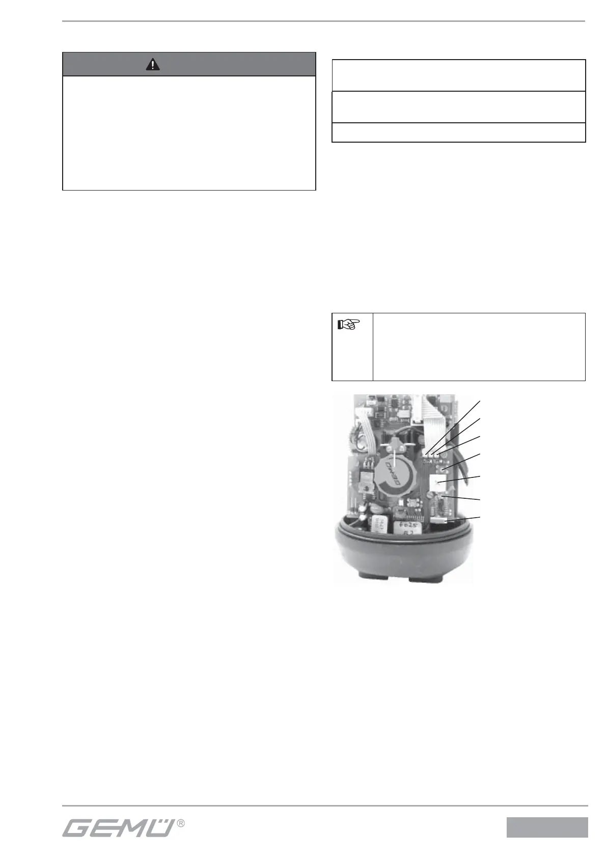
All operating and display elements are
located on the side of the unit as depicted
in the photo below. All live elements are on
the opposite side of the transmission and
are protected by a foil against accidental
contact.
In the event of an operating error
or in order to abort, the mains plug
must be pulled in order to restart
the unit.
Left LED
Middle LED
Right LED
Upper button
16-level switch
for dead zone
Lower button
Slide switch SB30
The slide switch should remain in the
left position.
If it is pushed to the right, the factory setting
(set value 0-10 V / 4-20 mA) could be lost
If recalibrated, a signal with 0 / 4 mA and
20 mA would have to be fed.