52 / 64
613, 618
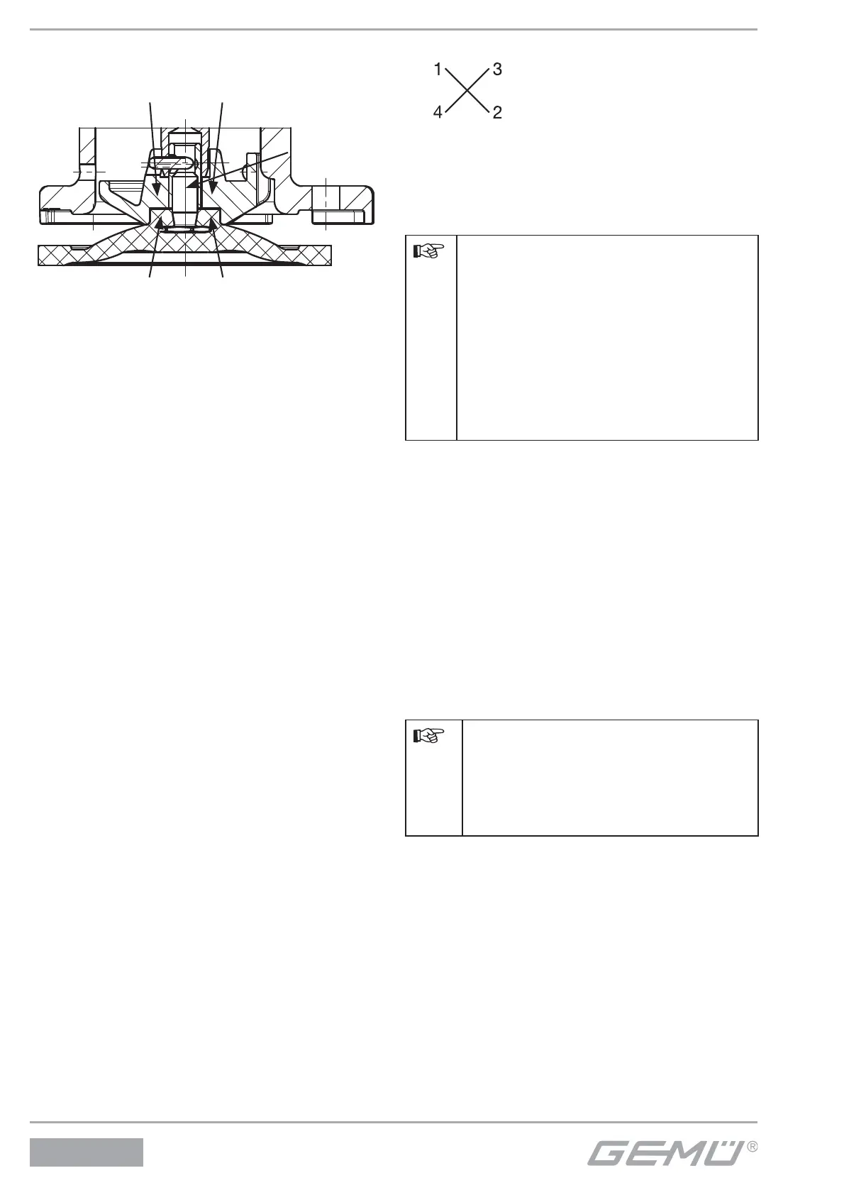
Diaphragm size 10
Threaded pin type diaphragm:
Diaphragm pin
Recess of compressor
Diaphragm boss
1. Move actuator A to the closed position.
2. Place the compressor loosely on the
actuator spindle, fi t the grooves into the
guides (see chapter 12.3.1 "General
information"). Diaphragm size 10: ensure
that the anti-twist system is engaged.
3. Check if the compressor fi ts closely in
the guides.
4. Screw new diaphragm tightly into the
compressor manually.
5. Check if the diaphragm boss fi ts closely
in the recess of the compressor.
6. If it is di cult to screw it in, check the
thread, replace damaged parts (only use
genuine parts from GEMÜ).
7. When clear resistance is felt turn back
the diaphragm anticlockwise until its bolt
holes are in correct alignment with the
bolt holes of the actuator.
13.4 Actuator mounting
on valve body
1. Move actuator A to the open position.
2. Open actuator A approx. 20 %.
3. Position actuator A with the mounted
diaphragm 2 on the valve body 1, take
care to align the compressor weir and
valve body weir (only for diaphragm
size 8).
4. Tighten bolts 18 with washers 19
by hand (hand tight only) (fastening
elements may vary dependent on
diaphragm size and / or valve body
version).
5. Fully tighten the bolts 18 diagonally.
6. Ensure that the diaphragm 2 is
compressed evenly (approx. 10-15 %,
visible by an even bulge to the outside).
7. Check tightness of completely
assembled valve.
Important:
Service and maintenance:
Diaphragms degrade in the course
of time. After valve disassembly /
assembly check that the bolts on
the body are tight and retighten
as necessary (GEMÜ 618: at the
very latest after the fi rst sterilisation
process).
13.5 Checking the valve seal
Install actuator into pipe (or testing
device).
Apply operating pressure to valve
(P = 6 bar).
Check / set seal by alternately turning
both transmission adjusting screws 1
(see photo page 50):
clockwise - tightness is increased
anticlockwise - tightness is decreased
Set the seal of the valve only as
high as absolutely necessary.
Setting the seal too high causes
unnecessary wear on the actuator
decreasing the life.
After checking the seal, both transmission
fastening screws 2 must be tightened in
order to fi x the transmission (see photo
page 50).
Replace cover (2 x SW10 screws).