PC/SC Guide
Prox–DU & Prox–SU
www.gemalto.com
DOC119811A Public Use Page 123/129
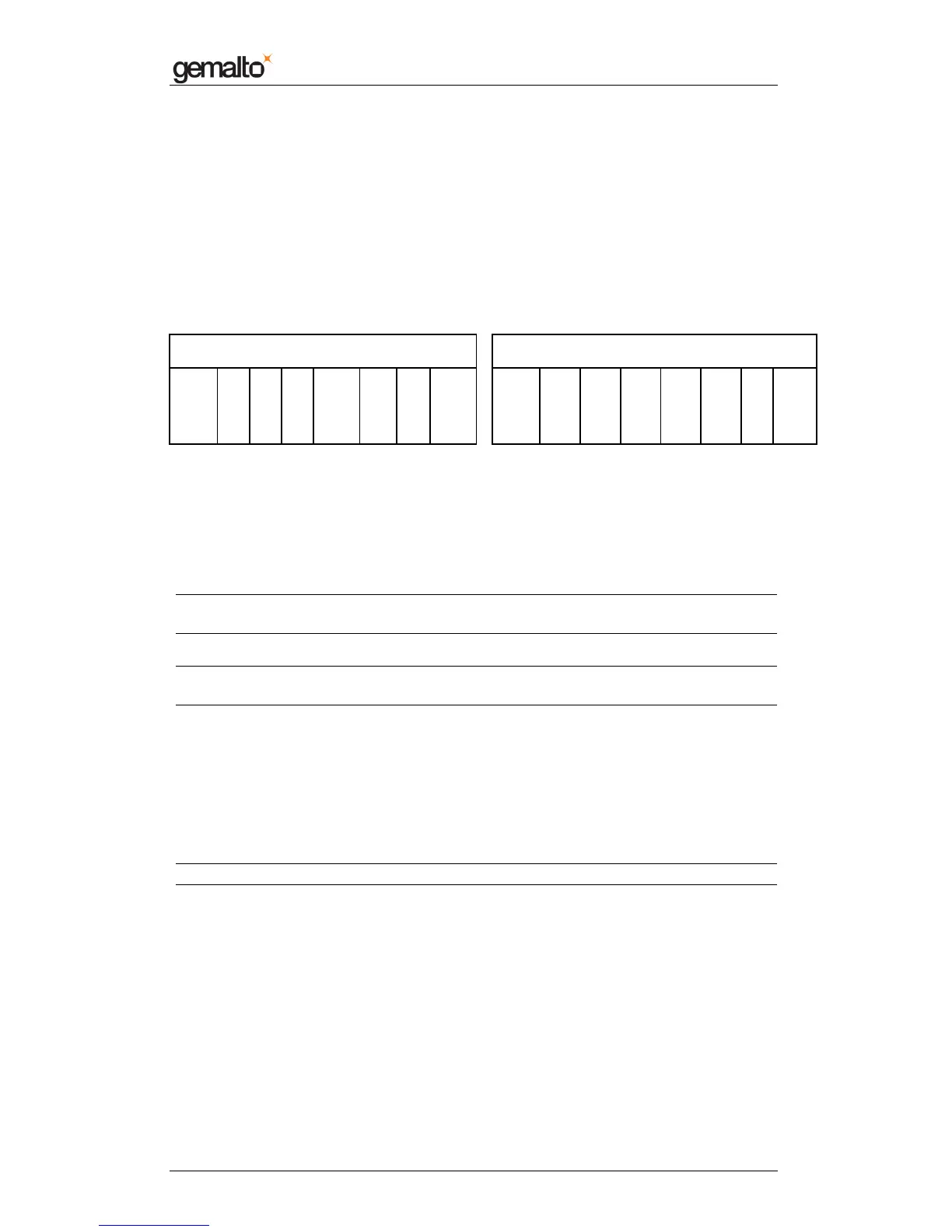
Lock Bytes Area
Lock0 and Lock1 represent the field-programmable read-only locking mechanism. Each
Page x from 3 (OTP) to 15 may be locked individually to prevent further write access by
setting the corresponding locking bit Lx to 1. After locking the page is read-only memory.
The 3 least significant bits of lock byte 0 are the block-locking bits. Bit 2 handles pages 15 to
10, bit 1 pages 9 to 4 and bit 0 page 3 (OTP). Once the blocking-locking bits are set the
locking configuration for the corresponding memory area is frozen - for example if BL15-10
is set to “1”, L15 to L10 (bit 7 to bit 2 of lock byte 2) can no longer be changed.
Lock0 byte Lock1 byte
MSB LSB MSB LSB
L7 L6 L5 L4 L
OTP
BL
15-
10
BL
9-
4
BL
OTP
L15 L14 L13 L12 L11 L10 L9 L8
Lx locks Page x to read-only
BLx blocks further locking for the memory area x
The locking and block-locking bits are set via standard write command to Page 2.
Bytes 2 and 3 of the write command and the actual contents of the lock bytes are bite-wise
“OR-ed” and the result then becomes the new contents of the lock bytes.
This process is irreversible. If a bit is set to “1”, it cannot be changed back to “0” again.
Note: The content of bytes 0 and 1 of Page 2 is not affected by the corresponding data
bytes of the write command.
Warning: To activate the new locking configuration after a write to the lock bit area, a new
smart card selection has to be carried out.
OTP Bytes Area
Page 3 is the OTP page. It is pre-set to all “0” (zeros) after production. These bytes may be
bit-wise modified by a write command.
The bytes of the write command of the current contents of the OTP bytes are bit-wise “OR-
ed” and the result becomes the new contents of the OTP bytes.
This process is irreversible. If a bit is set to “1”, it cannot be changed back to “0” again.
Note: This memory area may be used as a 32 ticks one-time counter.
Data Bytes Area
Pages 4 to 15 constitute the user read/write area. After production the data pages are
initialized to all “0” (zeroes).
MIFARE
®
UL Read/Write Operation
The MIFARE
®
Ultralight chip does not embed the MIFARE
®
Classic
security.
So no authentication operation is required before any read/write operation.

 Loading...