PART 4
ENGINE/DC CONTROL
Page 98
Section 4.3
Operational Analysis
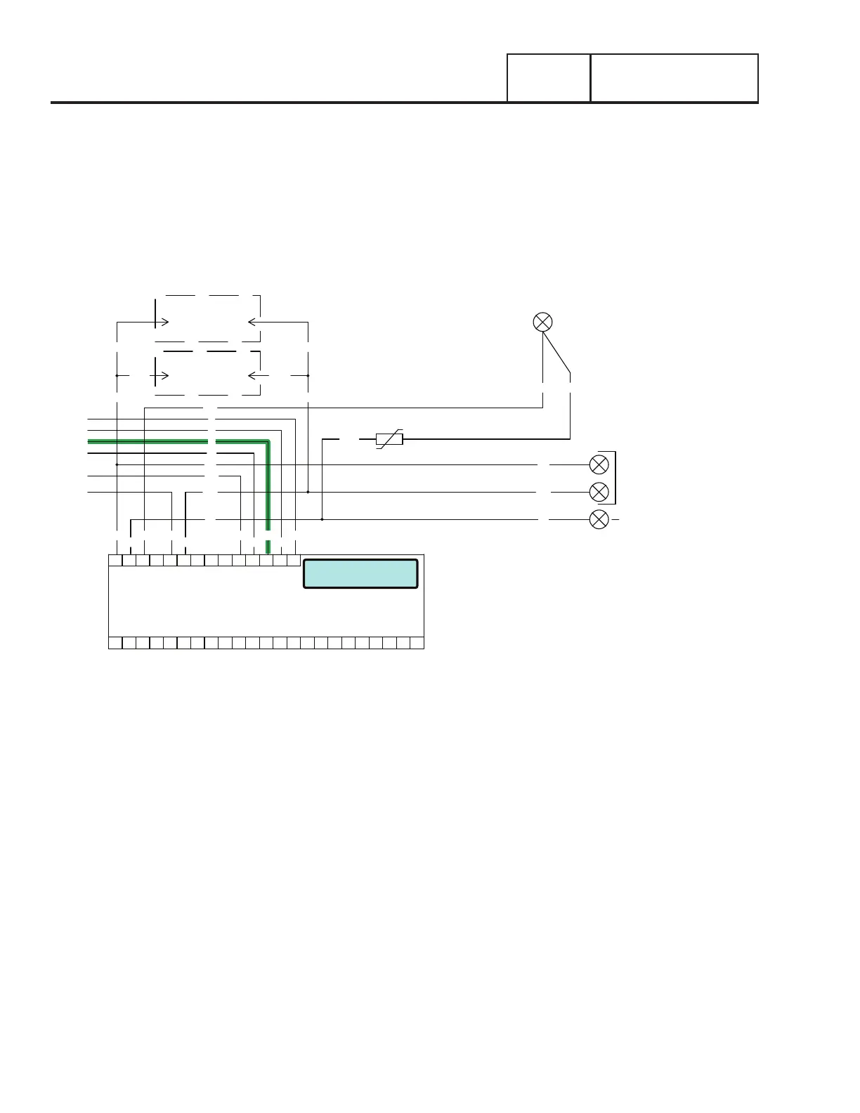
INITIAL DROPOUT OF UTILITY SOURCE VOLTAGE
Refer to Figure 96. Should a Utility power failure occur, circuit condition may be briefly described as follows:
•The controller continually monitors for acceptable Utility voltage via N1 and N2. Should Utility voltage drop below approximately
65% of the nominal source voltage, a programmable timer on the controller will turn on.
•In Figure 95, the 10-second timer is still timing and engine cranking has not yet begun.
•The AUTO-OFF-MANUAL switch is shown in the AUTO position. Battery voltage is available to the circuit board via Wire 13, the
7.5 amp fuse (F1). Wire 194 provides 12VDC to the transfer relay in the transfer switch.
NEUTRAL
INPUT
UTILITY
240 VAC
N1
T1
00 2
N2
44
11
0
4
6
T1
N2
N1
T1
N2
N1
00
6
4
0
11
44
LOAD SUPPLY
120 VAC
WHT00
MOV
T1A
N2AN1A
N2N1
1
2 N2B
N1B
1
CONNECT
240Vac
2
BATTERY WARMER
OPTIONAL
CONNECT
240Vac
OIL WARMER
OPTIONAL
BATTERY CHARGER
Utility Dropout
Pausing 10 seconds
J5
PRINTED CIRCUIT BOARD
CONTROLLER
J4
18171615141312109 1186 721 43 5 2322212019
141312109 1186 721 43 5
Figure 95.
 Loading...


