Page 86
PART 3
TRANSFER SWITCH
Section 3.4
Diagnostic Tests
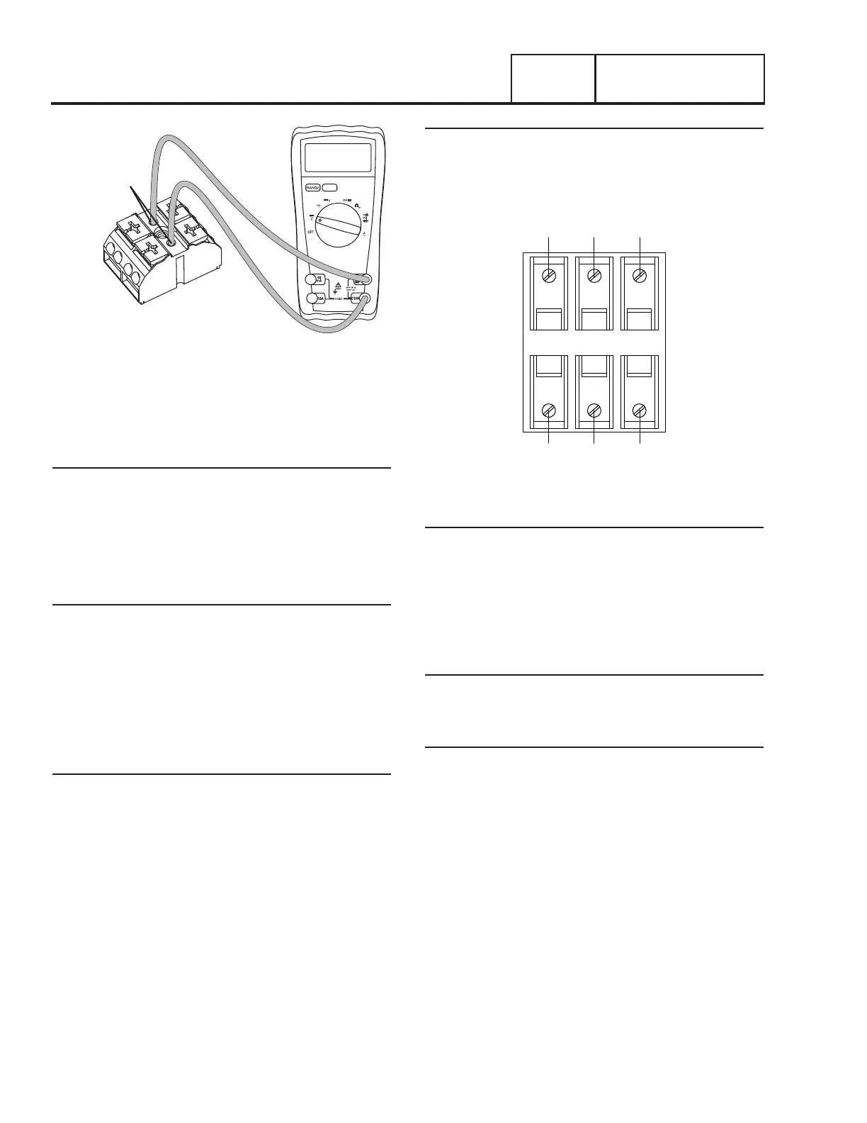
Figure 81. Terminal Block Test Points
TEST 34 – CHECK UTILITY SENSING
VOLTAGE AT THE CIRCUIT BOARD
Discussion
If the generator starts and transfer to STANDBY occurs in the
automatic mode when acceptable UTILITY source voltage is
available at the terminal block, the next step is to determine if
sensing voltage is reaching the controller.
Note: The System Ready LED will flash in AUTO or UTILITY
LOST will display on the panel.
Procedure
1. Set the AUTO-OFF-MANUAL switch to OFF.
2. Disconnect the J5 connector from the controller.
3. Set a VOM to measure AC voltage.
4. Connect one meter test lead to Wire N1. Connect the
other meter test lead to Wire N2. Approximately 240 VAC
should be measured. See Figure 82.
Results
1. If voltage was measured in Step 4 and the pin connections
are good, replace the circuit board.
2. If voltage was NOT measured in Step 4, repair or replace
Wire N1/N2 between connector and terminal block.
TEST 35 – CHECK UTILITY SENSE VOLTAGE
The N1 and N2 terminals in the transfer switch deliver utility
voltage “sensing” to a circuit board. If voltage at the terminals
is zero or low, standby generator startup and transfer to the
“Standby” source will occur automatically as controlled by the
circuit board. A zero or low voltage at these terminals will also
prevent retransfer back to the “Utility” source.
Procedure
With utility source voltage available to terminal lugs N1 and N2,
use a VOM to test for utility source line-to-line voltage across
terminal locations N1 and N2 terminals. Normal line-to-line
utility source voltage should be indicated.
N2
N1
N1A N2A T1A
F1 F2 F3
A A A
B B B
T1
Figure 82. Transfer Switch Fuse Block
Results
1. If voltage reading across the N1 and N2 terminals is zero
or low, refer to Flow Chart.
2. If voltage reading is good, refer to Flow Chart.
TEST 36 – CHECK T1 WIRING
Discussion2
If the T1 wiring is shorted to ground can cause the F3 fuse to
blow.
Procedure
1. Set the AUTO-OFF-MANUAL to the OFF position.
2. Remove F1, F2, and F3 from the fuse holder in the transfer
switch.
3. Disconnect the J5 connector from the controller.
4. Set the Volt-Ohm-Milliammeter (VOM) to measure
resistance.
a. Connect one meter test lead to T1 on the customer
connection in the Generator and the other meter lead to
ground. Measure and record the resistance.
b. Connect one meter test lead to T1 on the customer
connection in the Generator and the other meter test
lead to Wire 194. Measure and record the resistance.
c. Connect one meter test lead to T1 on the customer
connection in the Generator and the other meter test
lead to Wire 23. Measure and record the resistance.
 Loading...


