PART 3
TRANSFER SWITCH
Page 62
Section 3.1
Description and Components
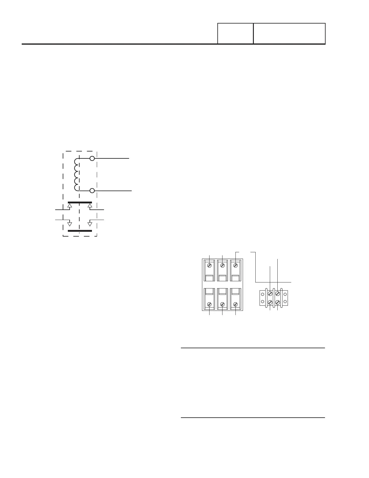
b. The controller’s logic holds the Wire 23 circuit open
to ground (Normally Open circuit) and the relay is
de-energized.
c. When de-energized, the relay contacts are in their
normal condition (one set open, N.O.; and one set
closed, N.C.)
d. The normally closed relay contacts deliver Utility source
power to the utility closing circuit of the transfer switch.
e. The normally open relay contacts will deliver Standby
source power to the transfer switch standby closing
circuit only when the Transfer Relay is energized by the
control panel.
Figure 63. Transfer Relay Schematic
2. During automatic system operation, when the Generator
controller “senses” that Utility source voltage has dropped
out, the controller will initiate a ten second “Line Interrupt
Delay” timer; at the end of the ten second delay the
controller will crank and start the engine.
3. When the circuit board “senses” that the engine has
started (via wire 18 from the magneto circuit), the
controller will initiate a five second “Engine Warm-up
Timer.”
4. When the “engine warm-up timer” has timed out, the
controller’s logic closes the Wire 23 circuit to ground.
a. The transfer relay energizes.
b. The relays normally closed contacts open and its
normally open contacts close.
c. When the normally open contacts close, Standby
source power is delivered to the standby closing coil
and transfer to “Standby” occurs.
5. When the controller “senses” that Utility source voltage
has been restored (above 75% of nominal for 15
seconds), the Wire 23 circuit will open from ground.
a. The transfer relay will de-energize, its normally closed
contacts will close and its normally open contacts will
open.
b. When the normally closed relay contacts close, utility
source voltage is delivered to the utility closing coil to
energize that coil.
c. Transfer back to UTILITY occurs.
NEUTRAL LUG
The Generator is equipped with an UNGROUNDED neutral. The
neutral lug in the transfer switch is isolated from the switch
enclosure.
MANUAL TRANSFER HANDLE
The manual transfer handle is retained in the transfer switch
enclosure by means of a wing nut and stud. Use the handle to
manually move the CONTACTOR to the “Utility” or “Standby”
position.
Instructions on use of the manual transfer handle are located in
Section 5.1 “Operational Tests and Adjustments”.
CUSTOMER CONNECTIONS
During system installation, this 3-point terminal block must
be properly interconnected with an identically labeled terminal
block in the generator customer connections box.
Figure 64 identifies the customer connections located in the
transfer switch. The wires are identified as 194, 23, N1, N2, T1.
F3
TB1
F1 F2
N2
N1
B BB
N1A
A A A
N2A
23
23
194
T1
194
T1A
Figure 64. Customer Connections
Utility N1 and N2
N1 and N2 provide the Utility voltage-sensing signal to the
controller. The controller utilizes the sensing circuit as
follows:
•If Utility source voltage should drop below 65% of nominal
for ten seconds, the controller’s logic will initiate automatic
cranking and startup. The controller will transfer the switch
to the Standby position after a five second engine warm-up
timer.
Load T1
Wire T1, connected to the Load side of the CONTACTOR,
provides 120 VAC for the battery charging circuit (the battery
charge is an integral component of the controller). The charger
maintains battery voltage anytime the load terminals have
voltage available.
 Loading...


