Page 142
PART 4
ENGINE/DC CONTROL
Section 4.5
Diagnostic Tests
TEST 82 – TEST F3 FUSE CIRCUIT
Procedure
1. Set a Volt-Ohm-Milliammeter (VOM) to measure AC
voltage.
2. Connect one meter test lead to the top side of the T1 fuse
holder and connect the other test lead to the NEUTRAL
connection. Measure and record the voltage.
a. If the VOM indicated 120 VAC, proceed to Step 3.
b. If the VOM indicated less than 120 VAC or 0, verify
that Load voltage is available to the LOAD side of the
CONTACTOR.
3. On the generator panel, set the AUTO-OFF-MANUAL switch
to the OFF position.
4. Disconnect Utility from the transfer switch.
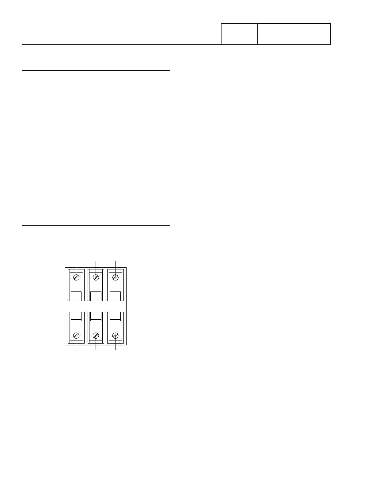
5. Remove fuse F3 from the fuse holder. (see Figure 160).
6. Inspect and test fuses for an OPEN condition with a Volt-
Ohm-Milliammeter (VOM) set to measure resistance,
CONTINUITY should be measured across the fuse.
Results
1. Replace blown fuse as needed and proceed to Problem 10
“Blown T1 Fuse”
N2
N1
N1A N2A T1A
F1 F2 F3
A A A
B B B
T1
Figure 160. Transfer Switch Fuse Block
 Loading...


