GENERAL INFORMATION
PART 1
Section 1.2
Installation Basics
Page 11
INTRODUCTION
Information is provided in this section to ensure the service
technician will have a basic knowledge of installation
requirements for home standby systems. Installation problems
that arise often relate to poor or unauthorized installation
practices.
A typical home standby electric system is shown in Figure 7.
Installation of a system includes the following:
•Selecting a location
•Grounding the Generator
•Providing the fuel supply
•Mounting the load center
•Connecting power source and load lines
•Connecting system control wiring
•Post installation tests and adjustments
SELECTING A LOCATION
Install the Generator set as close as possible to the electrical
load distribution panel(s) that will be powered by the unit,
ensuring that there is proper ventilation for cooling air and
exhaust gases. This will reduce wiring and conduit lengths.
Wiring and conduit not only add to the cost of the installation,
but excessively long wiring runs can result in a voltage drop.
Control system interconnections between the transfer switch
and Generator consists of N1, N2, T1, 194, and 23. In addition,
a Wire 0 must be connected for use with Nexus Smart Switches.
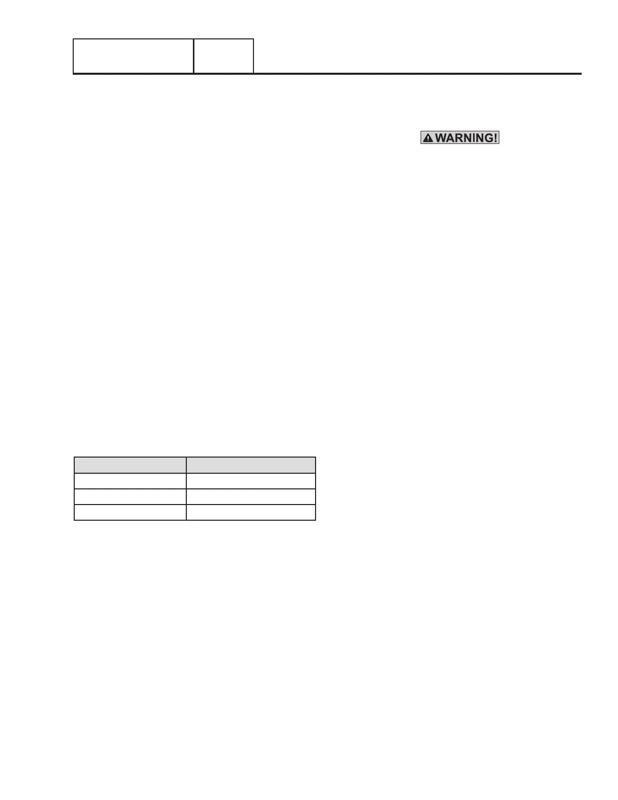
Control system interconnection leads must be run in a conduit
that is separate from the AC power leads. Recommended wire
gauge size depends on length of the wire:
Max. Cable Length Recommended Wire Size
35 feet (10.67m) No. 16 AWG.
60 feet (I8.29m) No. 14 AWG.
90 feet (27.43m) No. 12 AWG.
NFPA 37 CODE REQUIREMENTS
The National Fire Protection Association (NFPA) has established
standards for the installation and use of stationary combustion
engines. This code limits the spacing of an enclosed Generator
set from a structure or wall. NFPA 37 states:
NFPA 37, Section 4.1.4, Engines Located Outdoors. Engines,
and their weatherproof housings if provided, that are installed
outdoors shall be located at least 5 feet from openings in walls
and at least 5 feet from structures having combustible walls. A
minimum separation shall not be required where the following
conditions exist:
1. The adjacent wall of the structure has a fire resistance
rating of at least 1 hour.
2. The weatherproof enclosure is constructed of
noncombustible materials and it has been demonstrated
that a fire within the enclosure will not ignite combustible
materials outside the enclosure.
Annex A — Explanatory Material
A4.1.4 (2) Means of demonstrating compliance are by means
of full-scale fire test or by calculation procedures.
Generator exhaust contains DEADLY carbon monoxide
gas. This dangerous gas can cause unconsciousness
or death. Do not place the unit near windows, doors,
fresh air intakes (furnaces, etc) or any openings in the
building or structure, including windows and doors of an
attached garage.
The air-cooled product line has under gone the required testing,
which meets the requirements of exception 2. The criteria for
the testing were to determine the worst-case fire scenario within
the Generator and to determine the ignitability of items outside
the engine enclosure at various distances. The enclosure is
constructed of non-combustible materials. The results and
conclusion from the independent testing lab indicated that any
fire within the Generator enclosure would not pose any ignition
risk to nearby combustibles or structures, with or without fire
service personnel response.
Based on the required testing, the requirement of NFPA 37,
Sect 4.1.4, the guidelines for the 8, 10, 12, 13, 14, 15, 16,
17 and 20kW units changed to 18 inches (457mm) from the
back side of the Generator to a stationary wall or building. For
adequate maintenance and airflow clearance, the area above
the Generator should be at least three (3) feet with a minimum
of three (3) feet at the front and ends of the enclosure. This
includes, but not limited to trees, shrubs, and vegetation that
could obstruct airflow. See Figures 1 and 6 for further details.
GROUNDING THE GENERATOR
The National Electric Code requires that the frame and external
electrically conductive parts of the Generator be properly
connected to an approved earth ground. Local electrical codes
may also require proper grounding of the unit. For that purpose,
a grounding lug is attached to the unit. Grounding may be
accomplished by attaching a stranded copper wire of the proper
size to the Generator grounding lug and to an earth-driven
copper or brass grounding-rod. Consult with local electrician
for grounding requirements in the area.
THE FUEL SUPPLY
Natural gas is the primary fuel source utilized for the operating,
testing and adjusting of units with air-cooled engine. When
it is necessary, it is possible to convert units with air-cooled
engines to use liquid propane vapor (LPV). See Section 1.4
“Reconfiguring the Fuel System” for the conversion procedure.
LPV gas is usually supplied as a liquid in high-pressure tanks.
The air-cooled product requires a “vapor withdrawal” type of
fuel supply system when Liquid Propane (LP) gas is used. The
“vapor withdrawal” system utilizes the gaseous fuel vapors that
form at the top of the supply tank.
The pressure at which LP is delivered to the Generator may
 Loading...


