PART 4
ENGINE/DC CONTROL
Page 96
Section 4.3
Operational Analysis
INTRODUCTION
The “Operational Analysis” is intended to familiarize the service technician with the operation of the DC and AC control system. A
through understanding of how the system works is essential to sound and logical troubleshooting. The control system illustrations
on the following pages represent a 17kW unit.
UTILITY SOURCE VOLTAGE AVAILABLE
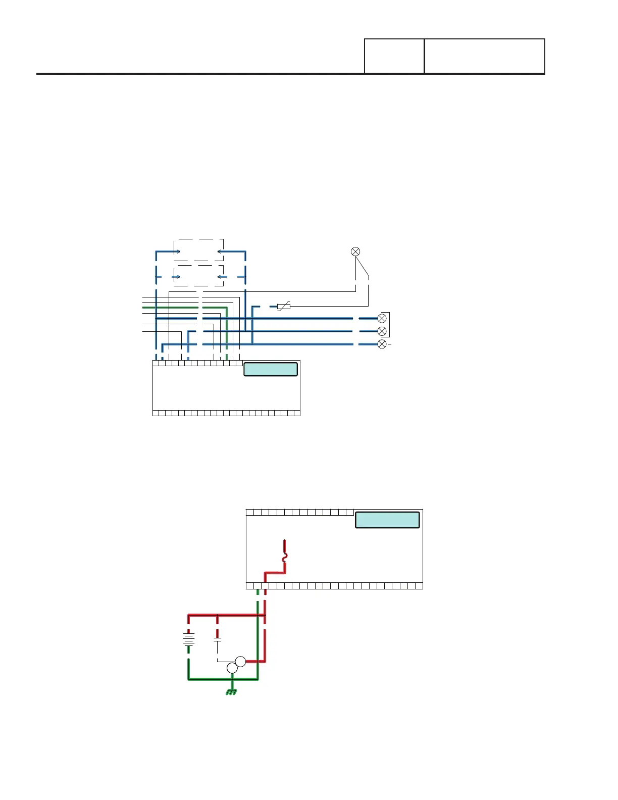
Refer to Figure 94. The circuit condition with the AUTO-OFF-MANUAL switch set to the AUTO position and with Utility source power
available can be briefly described as follows:
•Utility source voltage is available to the transfer switch Terminal Lugs N1 and N2 and the CONTACTOR is in the “Utility” position.
•Utility voltage is available to the controller via Wire N1 and N2 (see to Figure 92).
•Battery voltage is available to the controller via Wire 13 when a Battery is installed (see Figure 93).
NEUTRAL
INPUT
UTILITY
240 VAC
N1
T1
00 2
N2
44
11
0
4
6
T1
N2
N1
T1
N2
N1
00
6
4
0
11
44
LOAD SUPPLY
120 VAC
WHT00
MOV
T1A
N2AN1A
N2N1
1
2 N2B
N1B
1
CONNECT
240Vac
2
BATTERY WARMER
OPTIONAL
CONNECT
240Vac
OIL WARMER
OPTIONAL
BATTERY CHARGER
Running - Utility Loss
J5
PRINTED CIRCUIT BOARD
CONTROLLER
J4
18171615141312109 1186 721 43 5 2322212019
141312109 1186 721 43 5
0
BATTERY
0 13
16
13
SCR
SM
SC
13 13
Ready to Run
F1
TO PCB
J3
J5
PRINTED CIRCUIT BOARD
CONTROLLER
J4
18171615141312109 1186 721 43 5 2322212019
141312109 1186 721 43 5
Figure 92.
Figure 93.
 Loading...


