AC GENERATORS
PART 2
Page 51
TEST 5 – TEST SENSING CIRCUIT
WIRES 11 AND 44
Discussion
The voltage regulator (internal to the controller) requires a
reference voltage in order to regulate at a specific voltage and to
recognize if the alternator is producing voltage. The alternator
may be producing a voltage, but if the voltage regulator cannot
“sense” the voltage, it will fault out for under-voltage. This test
will verify the integrity of the sensing circuit.
Required Tools
•Meter test leads that are capable of measuring voltage inside
a connector without damaging the socket. A set of black
and red test leads for this application are available from the
manufacturer. Contact your nearest servicing dealer for more
information. See Figure 47.
Note: It is not recommended to use any testing device other
than the manufactures approved test lead adapters.
Procedure
1. Remove the 7.5 amp fuse from the control panel.
2. Remove the controller and the cover to expose the lower
harness connections.
3. Disconnect the J5 connector from the controller.
4. Set the Volt-Ohm-Milliammeter (VOM) to measure
resistance.
Note Stator winding resistance values are very low and
some VOM’s will not read such a low resistance, and
will simply indicate different ranges of resistance. The
manufacture recommends a high quality digital type meter
capable of reading a very low resistance.
5. Connect one-meter test lead to J5 Pin 11 (Wire 11) and
the other meter test lead to the NEUTRAL connection.
Measure and record the resistance.
6. Connect one-meter test lead to J5 Pin 10 (Wire 44) and
the other meter test lead to the NEUTRAL connection.
Measure and record the resistance.
a. If the meter indicated a resistance value of less than
0.2 ohms in Steps 5 and 6, stop testing and refer back
to the flow chart (Good).
b. If the meter indicated OPEN in Steps 5 or 6, proceed to
Step 7.
7. Disconnect the lower bulkhead C1 connector (Figure 52).
8. Connect one-meter test lead to C1 Pin 2 (Wire 11) and
the other meter test lead to the NEUTRAL connection,
measure and record the resistance.
Section 2.4
Diagnostic Tests
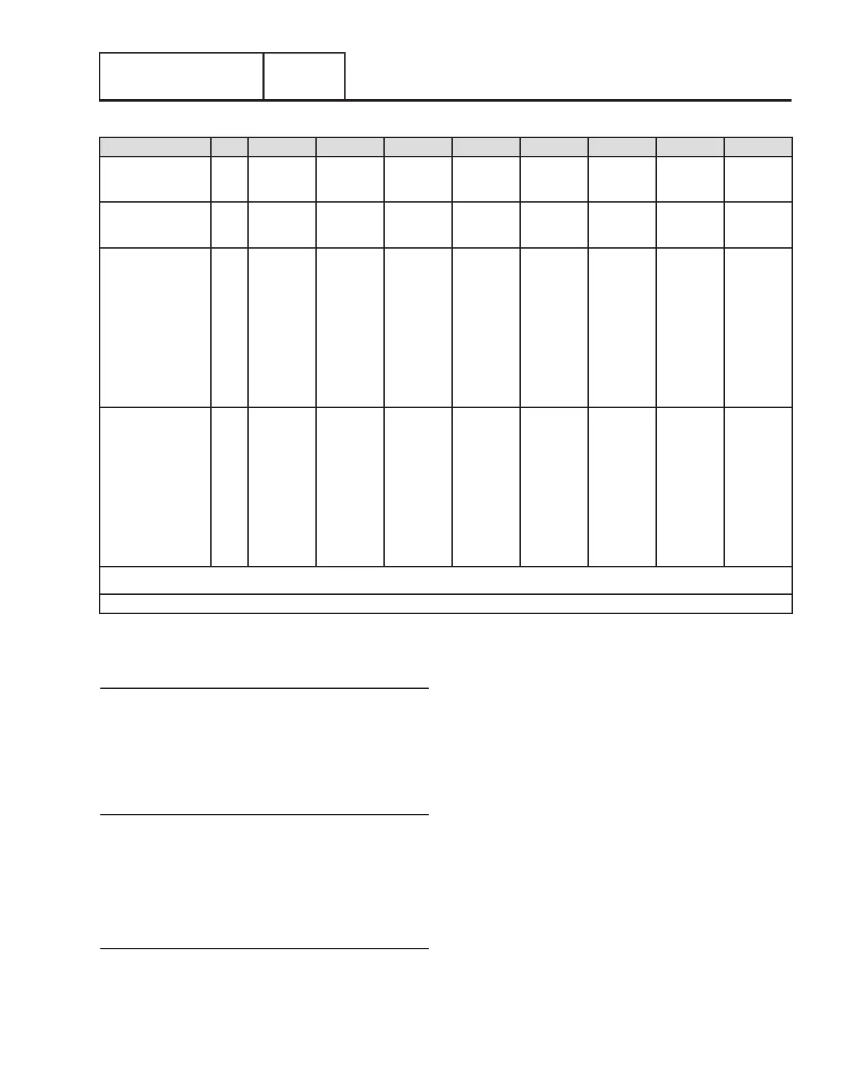
Results: Size A B C D E F G H
Voltage Results
Wire 2 & 6
ALL
Above 50
VAC
Above 50
VAC
Below 50
VAC
Zero or
Residual
Volts
Below 50
VAC
Below 50
VAC
Above 50
VAC
Below 50
VAC
Voltage Results
Wire 11 & 44
ALL
Above 50
VAC
Below 50
VAC
Above 50
VAC
Zero or
Residual
Volts
Below 50
VAC
Below 50
VAC
Above 50
VAC
Below 50
VAC
Static Rotor Amp Draw
8kW
10kW
12kW
14kW
15kW
16kW
17kW
20kW
1.76-2.05
1.76-2.05
1.46-1.70
1.46-1.70
1.33-1.54
1.33-1.54
1.33-1.54
1.16-1.36
1.76-2.05
1.76-2.05
1.46-1.70
1.46-1.70
1.33-1.54
1.33-1.54
1.33-1.54
1.16-1.36
1.76-2.05
1.76-2.05
1.46-1.70
1.46-1.70
1.33-1.54
1.33-1.54
1.33-1.54
1.16-1.36
Zero Current
Draw
Above 2.5A
Above 2.5A
Above 2.3A
Above 2.3A
Above 2.3A
Above 2.3A
Above 2.3A
Above 2.0A
1.76-2.05
1.76-2.05
1.46-1.70
1.46-1.70
1.33-1.54
1.33-1.54
1.33-1.54
1.16-1.36
Zero Current
Draw
1.76-2.05
1.76-2.05
1.46-1.70
1.46-1.71
1.33-1.54
1.33-1.54
1.33-1.54
1.16-1.36
Running Rotor Amp
Draw
8kW
10kW
12kW
14kW
15kW
16kW
17kW
20kW
1.76-2.05
1.76-2.05
1.46-1.70
1.46-1.70
1.33-1.54
1.33-1.54
1.33-1.54
1.16-1.36
1.76-2.05
1.76-2.05
1.46-1.70
1.46-1.70
1.33-1.54
1.33-1.54
1.33-1.54
1.16-1.36
1.76-2.05
1.76-2.05
1.46-1.70
1.46-1.70
1.33-1.54
1.33-1.54
1.33-1.54
1.16-1.36
Zero Current
Draw
Above 2.5A
Above 2.5A
Above 2.3A
Above 2.3A
Above 2.3A
Above 2.3A
Above 2.3A
Above 2.0A
1.76-2.05
1.76-2.05
1.46-1.70
1.46-1.70
1.33-1.54
1.33-1.54
1.33-1.54
1.16-1.36
Zero Current
Draw
Above 2.5A
Note: Actual values measured may vary by as much as .5 amps; depending on the type and quality of meter used, the condition of the unit, and how good the
connection is between the test leads and test points.
ç
MATCH RESULTS WITH LETTER AND REFER TO FLOW CHART IN SECTION 2.3 “Problem 1”
è
Table 10. TEST 4 Results – Fixed Excitation Test/Rotor Amp Draw Test (8-20kW)
 Loading...


