ENGINE/DC CONTROL
PART 4
Page 123
Section 4.5
Diagnostic Tests
(propane) gas is heavier than air, and tends to settle
in low areas. Even the slightest spark can ignite these
gases and cause an explosion.
Procedure
A water manometer or a gauge that is calibrated in “ounces per
square inch” may be used to measure the fuel pressure. Fuel
pressure at the inlet side of the fuel solenoid valve should be
between 5-7 inches water column for natural gas (NG) or 10-12
inches water column for LP gas.
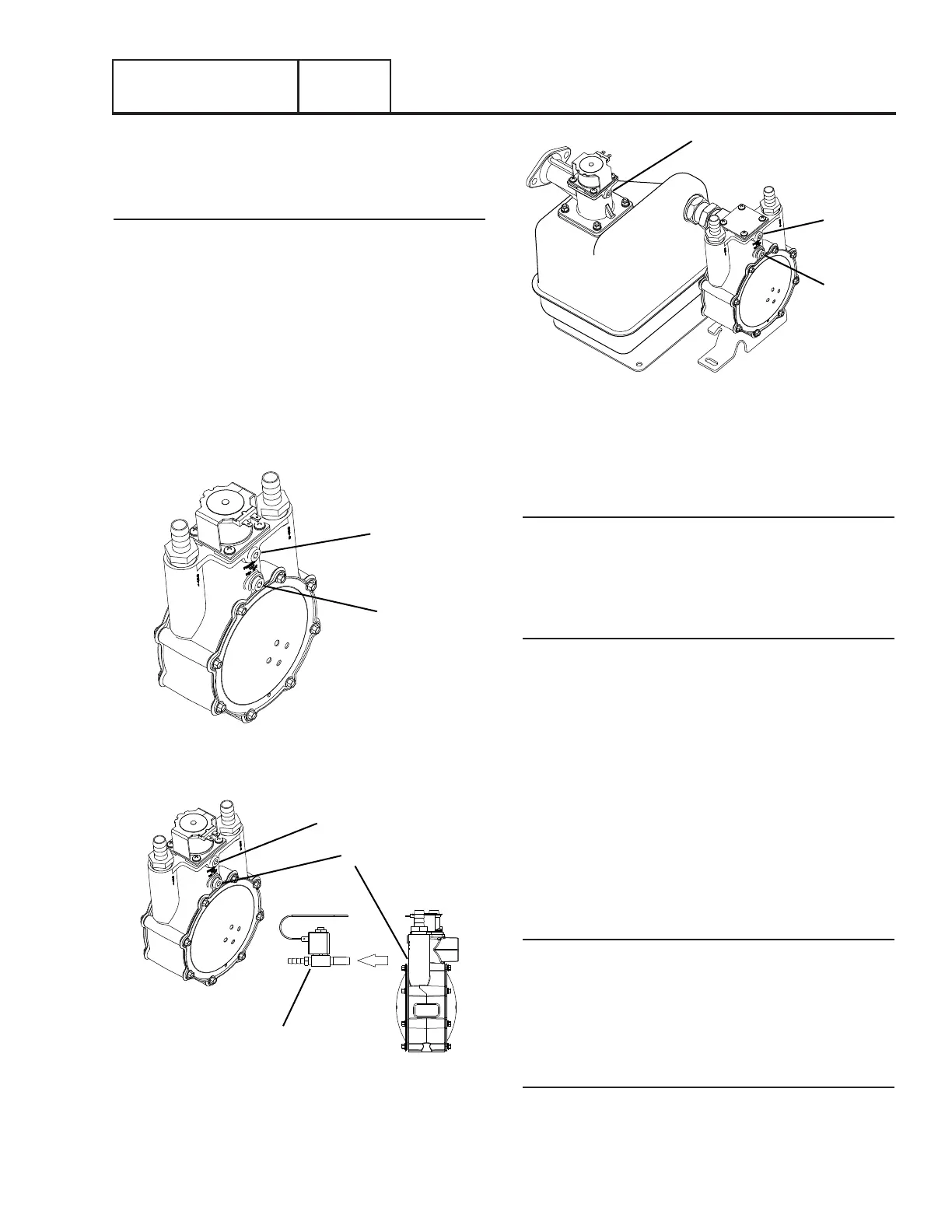
1. See Figures 124, 125 or 126 for the gas pressure test point
on the fuel regulator. The fuel pressure can be checked at
Port 1 on all fuel regulators, and at Port 3 on 12-20kW units.
2. With the manometer connected properly, crank the engine.
Nominal fuel pressure should be measured. If pressure is
not measured while cranking refer back to flow chart.
PORT 1
PORT 2
Figure 124. (8kW) Gas Pressure Test point
PORT 1
PORT 2
SOLENOID REMOVED
Figure 125. (10kW) Gas Pressure Test point
PORT 3
PORT 1
PORT 2
Figure 126. (12-20kW) Gas Pressure Test point
Note: Where a primary regulator is used to establish fuel
inlet pressure, adjustment of that regulator is usually the
responsibility of the fuel supplier or the fuel supply system
installer.
12-20kW Units Only
Note: The test port (Port 3) below the fuel solenoid may
be used to take a fuel pressure reading before the fuel
solenoid. Consistent pressure should be measured at this
port both while the generator is running and when the
generator is off.
Results
1. If fuel supply and pressure are adequate, but engine will
not start refer back to the flow chart.
2. If generator starts but runs rough or lacks power, repeat
the above procedure with the generator running and under
load. The fuel system must be able to maintain 10-12
inches water column at all load requirements for propane,
and 5-7 inches water column for natural gas. If proper
fuel supply and pressure is maintained, refer to Problem
17 Flow Chart.
TEST 51 – CHECK CONTROLLER WIRE 14
OUTPUTS
Discussion
During any crank attempt, the controllers crank relay and run
relays both are energized. When the run relay energizes, its
contacts close and 12 VDC is delivered to the Wire 14 circuit
and to the fuel solenoid. The solenoid energizes open to allow
fuel flow to the engine. This test will determine if the controller
is working properly.
Procedure
1. Set the AUTO-OFF-MANUAL switch to OFF.
2. Set a Volt-Ohm-Milliammeter (VOM) to measure DC
voltage.
 Loading...


