AC GENERATORS
PART 2
Page 53
Section 2.4
Diagnostic Tests
Procedure: Resistance Test
1. Disconnect Wires 11 and 44 from the main line circuit
breaker (MLCB).
2. Disconnect Wires 22 and 33 from the NEUTRAL
connection and separate the leads.
3. Disconnect the bulkhead C1 connector.
4. Make sure all of the disconnected leads are isolated from
each other and are not touching the frame during the test.
5. Set the VOM to measure resistance.
6. Measure and record the resistance values for each set
of windings between the A and B test points as shown in
Table 11. Record the results in Table 14.
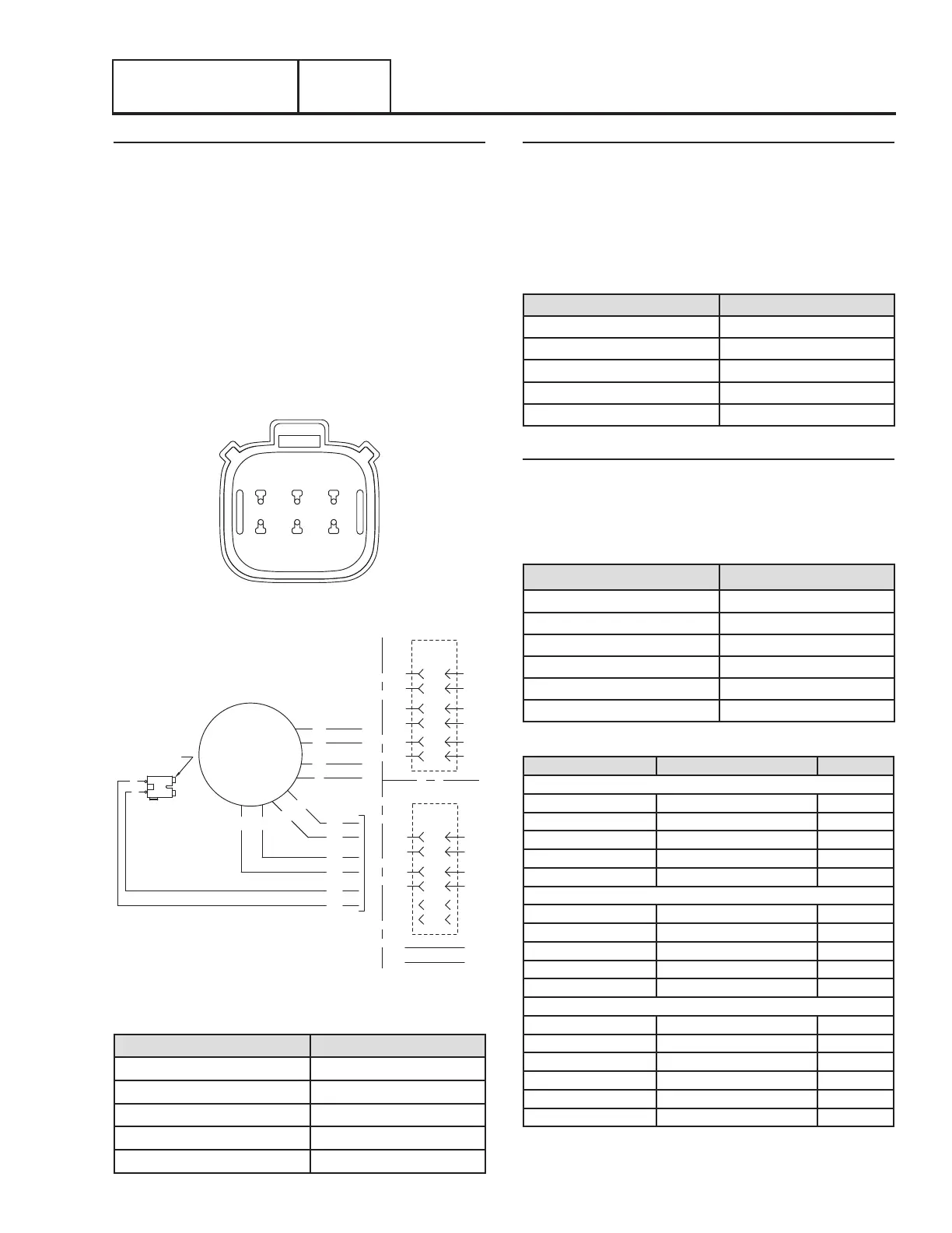
3 2 1
6 5 4
Figure 53. C1 Bulkhead Connector Pin Locations
BEARING
BA
0
4
44
22
33
11
STATOR
0
4
44
11
11
44
2 6
2
6
0
4
11
44
2
6
0
4
11
44
2
6
CLOSEST TO
6
5
2
1
4
3
PIN #
C1
TO C1 SEE TABLE FOR PINOUT
CONFIGURATION A
CONFIGURATION B
0
4
11
44
2
6
0
4
11
44
2
6
6
5
2
1
4
3
PIN #
C1
Figure 54. Stator Lead Connections
Table 11. Test Points
Test Point A Test Point B
Stator Lead Wire 11 Stator Lead 22
Stator Lead Wire 33 Stator Lead 44
C1 Pin 2 Wire 11 Stator Lead 22
C1 Pin 1 Wire 44 Stator Lead 33
C1 Pin 3 Wire 6 C1 Pin 4 Wire 2
Test Windings for a Short to Ground
7. Make sure all stator leads are isolated from each other
and are not touching the frame.
8. Measure and record the resistance values for each set
of windings between the A and B test points as shown in
Table 12. Record the results in Table 14.
Table 12. Test Points
Test Point A Test Point B
Stator Lead 11 Ground
Stator Lead 44 Ground
C1 Pin 1 Wire 44 Ground
C1 Pin 2 Wire 11 Ground
C1 Pin 4 Wire 2 Ground
Test For A Short Circuit Between Windings
9. Measure and record the resistance values for each set
of windings between the A and B test points as shown in
Table 13. Record the results in Table 14.
Table 13. Test Points
Test Point A Test Point B
C1 Pin 4 Wire 2 C1 Pin 2 Wire 11
C1 Pin 4 Wire 2 C1 Pin 2 Wire 44
C1 Pin 4 Wire 2 Stator Lead Wire 11
C1 Pin 4 Wire 2 Stator Lead Wire 44
Stator Lead 11 C1 Pin 1 Wire 44
Stator Lead 11 Stator lead Wire 44
Table 14. Test 7 Stator Results
Test Point A Test Point B Results
Resistance Tests
Stator Lead Wire 11 Stator Lead 22
Stator Lead Wire 33 Stator Lead 44
C1 Pin 2 Wire 11 Stator Lead 22
C1 Pin 1 Wire 44 Stator Lead 33
C1 Pin 3 Wire 6 C1 Pin 4 Wire 2
Shorts to Ground
Stator Lead 11 Ground
Stator Lead 44 Ground
C1 Pin 1 Wire 44 Ground
C1 Pin 2 Wire 11 Ground
C1 Pin 4 Wire 2 Ground
Shorted Condition
C1 Pin 4 Wire 2 C1 Pin 2 Wire 11
C1 Pin 4 Wire 2 C1 Pin 2 Wire 44
C1 Pin 4 Wire 2 Stator Lead Wire 11
C1 Pin 4 Wire 2 Stator Lead Wire 44
Stator Lead 11 C1 Pin 1 Wire 44
Stator Lead 11 Stator lead Wire 44
Note: These results may be needed when requesting factory
support.
 Loading...


