Site Selection and Preparation
Installation Guidelines for 60 Hz EcoGen™ Generator 13
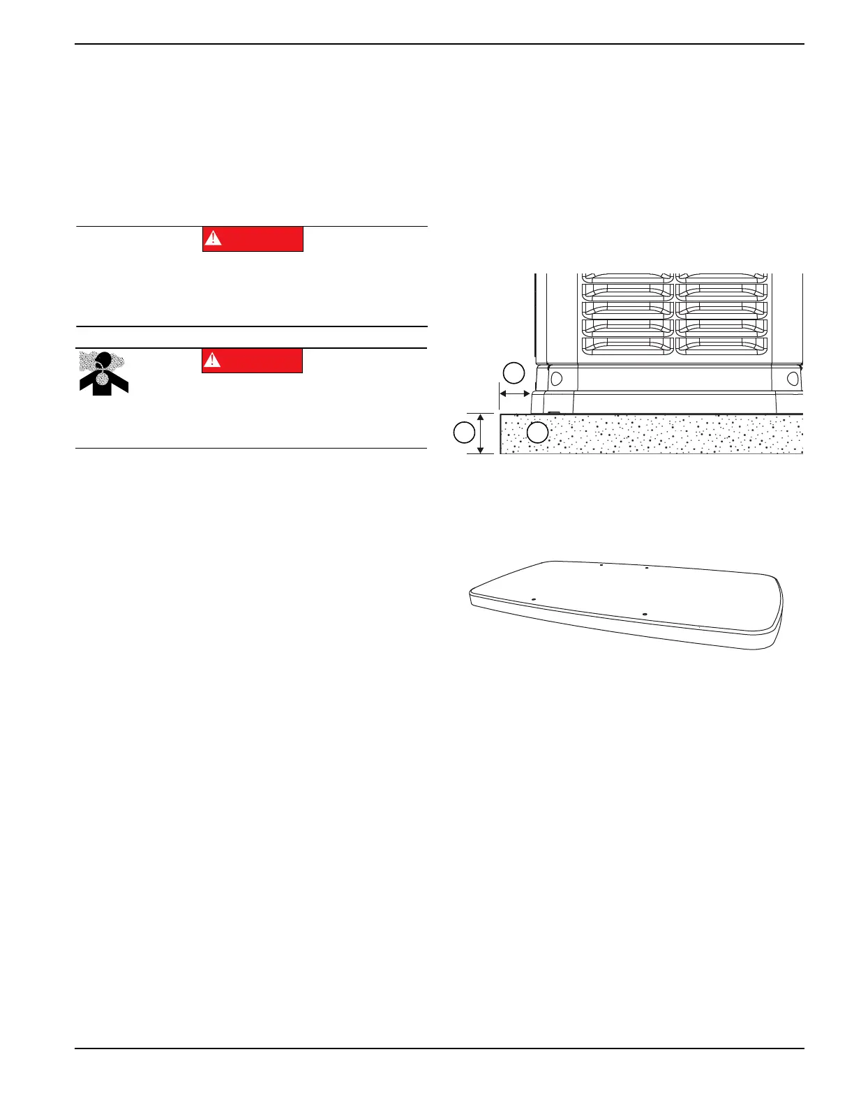
For adequate maintenance and airflow clearance, the
area above the generator should be at least 5 ft (1.52 m)
with a minimum of 3 ft (0.91 m) at the front and ends of
the enclosure. This would include trees, shrubs and
bushes. Vegetation not in compliance with these
clearance parameters could obstruct air flow. In addition,
exhaust fumes from the generator could inhibit plant
growth. See Figure 3-1 and the installation drawing
within the Owner’s Manual for details.
If the generator is not set to the OFF mode, it can crank
and start as soon as the battery cables are connected. If
the utility power supply is not turned off, sparking can
occur at the battery posts and cause an explosion.
Site Preparation
• Locate the mounting area as close as possible to the
transfer switch and fuel supply.
• Leave adequate room around the area for service
access (check local code), and place high enough to
keep rising water from reaching the generator.
• Choose an open space that will provide adequate
and unobstructed airflow.
• Place the unit so air vents won’t become clogged
with leaves, grass, snow or debris. Make sure
exhaust fumes will not enter the building through
eaves, windows, ventilation fans or other air intakes
(see Site Selection).
• Select the type of base, such as but not limited to
gravel or concrete, as desired or as required by local
laws or codes. Verify your local requirements before
selecting.
Material Sufficient for Level Installation
•
See Figure 3-3. Dig a rectangular area
approximately 5 in (127 mm) deep [A] and about 6 in
(152 mm) longer and wider [B] than the footprint of
the generator. Fill with 4 in (102 mm) of pea gravel
[C], crushed stone or any other non–combustible
material sufficient for level installation. Compact and
level the material. A concrete pad can be poured if
desired or required. The pad should be 4–5 in (102–
127 mm) thick and extend 6 in (152 mm) beyond the
outside of the generator in all directions.
Figure 3-3. Compacted Gravel Pad
NOTE: If a concrete pad is required, follow all applicable
federal, state or local codes.
Figure 3-4. Poured or Pre–formed Concrete Pad
Transportation Recommendations
Use a two wheeled hand cart or metal rails to carry the
generator (including the wooden pallet) to the installation
site. Place cardboard between the hand cart and the
generator to prevent any damage or scratches to the
generator.
Automatic start-up. Disconnect normal power source
and render unit inoperable before working on unit.
Failure to do so will result in death or serious injury.
(000236)
DANGER
Asphyxiation. Running engines produce
carbon monoxide, a colorless, odorless,
poisonous gas. Carbon monoxide, if not
avoided, will result in death or serious injury.
(000103)
DANGER
000611a
 Loading...