Electrical Connections
24 Installation Guidelines for 60 Hz EcoGen™ Generator
Control Wiring Notes
•
To separate low voltage from high voltage wires,
u
nless NEC Section 300.3(c)(1) requirements ar
e
me
t, run 2–wire start, N1, N2, and T1 wires through
wire shielding provided (see Parts Shipped Loose).
• Regardless of whether unit is running or not, keep T1
connected and energized with 120 VAC to keep
battery charged.
• Supplying 240 volts to N1 and N2 on EcoGen is only
for the Generac Cold W
eather Kit.
• The single pole breaker used for T1 may be removed
if a #14 jumper wire is installed from N2 to T1 (factory
side).
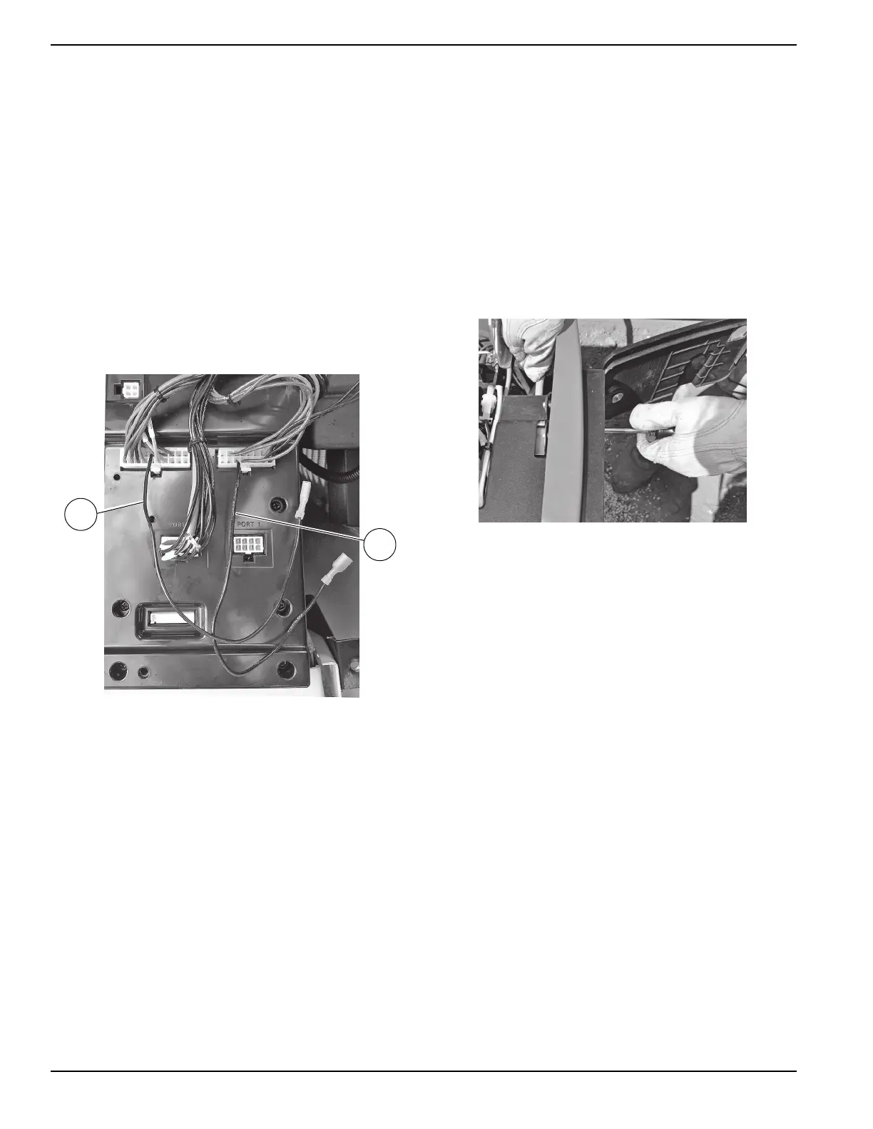
2–Wire Start Wire Connections
See Figure 6-2. Connect wires 183 and 178 as shown.
Figure 6-2. 2–Wire Start Wire Connections
Main AC Wiring
NOTE: Main AC wiring must be in accordance with local
jurisdiction and codes.
1. Strip the insulation off the wire ends. Do not
remove excessive insulation.
2. Remove the two cap plugs located behind the
br
eaker door and to the right of the Main Breaker.
3. Loosen the lugs of the Main Breaker through the
access
holes.
4. See Figure 6-3. Insert a power wire (E1 or E2)
th
rough the opening in the back cover and into th
e
bo
ttom lug. Torque to the proper specification.
.
Figure 6-3. Inserting Power Wire (E1 or E2)
5. There are three screws inside the top of the
breaker panel (behind the breaker door)
.
Removing these sc
rews will allow the
entire
br
eaker box to be carefully pulled out. When
reinstalling, be certain that the tabs
on the bottom
lock into place.
6. Connect the Neutral wire to the Neutral Lug if
a
pplicable. Torque to the required specification.
See Table 6.3.
7. Connect the Ground wire to the Ground Lug and
torque to the required specification. See Table 6.3.
NOTE: Neutral Bonding—For installations that require
the neutral to be bonded to the ground, this is done at the
customer connections terminals inside the generator.
Connect a suitably sized wire from the neutral bar to the
ground bar. This is normally required when the generator
is the source in a separately derived system. It is not
required when the generator is a backup source in a
normal power source-supplied electrical system with a 2–
pole transfer switch.
NOTE: Torque all wiring lugs, bus bars and connection
points to the proper torque specifications. Torque
specifications for the Main Line Circuit Breaker (MLCB)
can be found on a decal located on the inside of the Main
Line Circuit Breaker Door.
 Loading...