Electrical Connections
Installation Guidelines for 60 Hz EcoGen™ Generator 23
Section 6: Electrical Connections
Generator Connections
NOTE: Wiring must be performed in accordance with
local jurisdiction and codes.
1. Remove the appropriate Main AC/Control Wiring
knock–out plug at back of generator.
2. Install the generator feeder and control wiring
between the generator and inverter or electrical
loads to be powered by the generator per the
applicable NEC codes for the wiring method
selected. For knock–out plug locations (verify
specific transfer wiring and connections per
model), see Figure 2-7.
NOTE: This wiring can be run in the same conduit if the
appropriate insulation rated wire is used.
3. Seal the conduit at the generator in compliance
with any codes.
4. Strip insulation from wire ends. Do not remove
excessive insulation.
5. To connect the control wires, push down on the
spring loaded connection point with a flat head
screwdriver, insert wire and release.
NOTE: No wire insulation should be in the connection
point; only bare wire.
NOTE: The system is equipped with a 2–wire start to
facilitate connection to the inverter system.
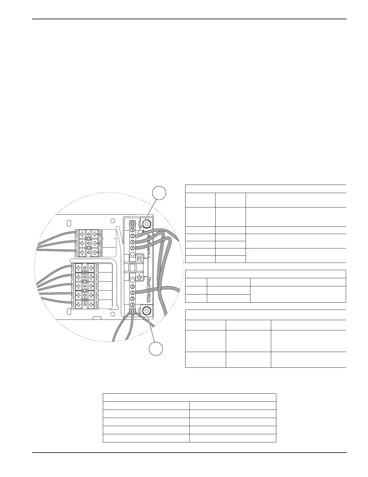
Control Wiring
Figure 6-1. Control Wiring Connections
Table 6.1: Control Pad Connections
Wire Color
Terminal /
Wire
Wire Description
Blue T1
120 VAC for Battery Charger
Single Pole 15 Amp Breaker
(see Control Wiring Notes)
Black 0 DC (–) Common Ground Wire
Yell ow N1
240 VAC for Cold Weather Kit (Utility Sense)
2 Pole 15 Amp Breaker
Yell ow N2
Blue 209
Common Alarm: Optional Alarm Relay
Contacts (Normally Open)
Blue 210
Table 6.2: 2–Wire Start Wire Connections
Wire Connection
Location
178 Female Faston
Hanging from controller above battery
compartment
183 Female Faston
Table 6.3: Control Wiring Torque Specifications
Location Wire Size
Torque Specification
A
4–6 AWG
8 AWG
10–14 AWG
35 in-lbs (4 Nm)
25 in-lbs (2.8 Nm)
20 in-lbs (2.3 Nm)
B
(Large Ground)
2/0 to 14 AWG
120 in-lbs (14 Nm)
SENSE
N1
UTILITY
209
COMMOM
ALARM
210
COMMON
ALARM
0
DC COMMON
194
+12 VDC
23
TRANSFER
T1
VAC LOAD
SUPPLY
N2
UTILITY
001463
Table 6.4: Control Wire and Two–Wire Start Length and Size
Maximum Wire Length Recommended Wire Size
1–115 ft (1–35 m) No. 18 AWG
116–185 ft (36–56 m) No. 16 AWG
186–295 ft (57–89 m) No. 14 AWG
296–460 ft (90–140 m) No. 12 AWG
 Loading...