Section 1 - General information
Air-cooled Generators
GENERAL
NFORMATON
NOTE:
A minimum of one approved manual shut-off valve
must be installed in the gaseous fuel supply line.
The valve must be easily accessible, Local codes
determine the proper location.
l.lO RECONFIGURINGTHE
FUELSYSTEM
O 1.10.1 8 KW 410CC ENGINE
To reconfigure the fuel system from NG to LR follow
these steps (Figure 1.4):
NOTE:
The primary regulator for the propane supply is
NOT INCLUDED with the generator, A fuel pres-
sure of I0 to 12 inches of water column (0,36 to
0.43 psi) to the fuel inlet of the generator MUST
BE SUPPLIED,
1. Turn off the main gas supply (if connected).
2. Open the roof and remove the door.
3. Remove the battery (if installed).
4. Take the plastic T-handle fuel selector in the poly
bag supplied with the generator.
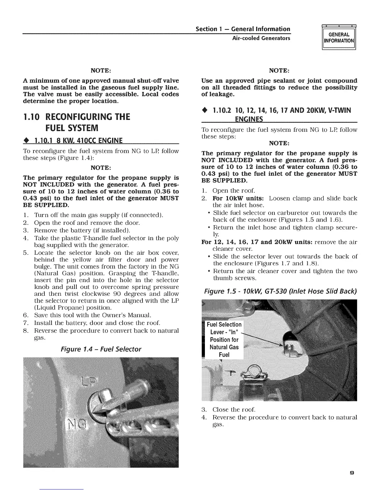
5. Locate the selector knob on the air box cover,
behind the yellow air filter door and power
bulge. The unit comes from the factory in the NG
(Natural Gas) position. Grasping the T-handle,
insert the pin end into the hole in the selector
knob and pull out to overcome spring pressure
and then twist clockwise 90 degrees and allow
the selector to return in once aligned with the LP
(Liquid Propane) position.
6. Save this tool with the Owner's Manual.
7. Install the battery, door and close the roof.
8. Reverse the procedure to convert back to natural
gas.
Figure 1.4 - Fuel Selector
NOTE:
Use an approved pipe sealant or joint compound
on all threaded fittings to reduce the possibility
of leakage,
0 1.10.2 10, 12, 14, 16, 17 AND 20KW, V=TWIN
ENGINES
To reconfigure the fuel system from NG to LR follow
these steps:
NOTE:
The primary regulator for the propane supply is
NOT INCLUDED with the generator, A fuel pres-
sure of I0 to 12 inches of water column (0,36 to
0.43 psi) to the fuel inlet of the generator MUST
BE SUPPLIED.
1. Open the roof.
2. For 10kW units: Loosen clamp and slide back
the air inlet hose.
* Slide fuel selector on carburetor out towards the
back of the enclosure (Figures 1.5 and 1.6).
* Return the inlet hose and tighten clamp secure-
ly.
For 12, 14, 16, 17 and 20kW units: remove the air
cleaner cover.
* Slide the selector lever out towards the back of
the enclosure (Figures 1.7 and 1.8).
* Return the air cleaner cover and tighten the two
thumb screws.
Figure 1.5 - lOkW, GT=530 (inlet Hose Slid Back)
FuelSelection
Lever- "in"
Positionfor
NaturalGas
Fuel
3. Close the roof.
4. Reverse the procedure to convert back to natural
gas.
9