Section 2 - Post Installation Start-up and Adjustments
Air-cooJedGenerators
POS%_
iNSTALLATiON
STAR.UP
ADJUSTMENTS
2.6 ENGINE GOVERNORADJUSTMENT
If both AC frequency and voltage are correspondingly
high or low, adjust the engine governor as follows:
• 2.6.1 8 KWUNITS
=_ WARNING
Z_ The engine must be OFF to perform steps I and
2.
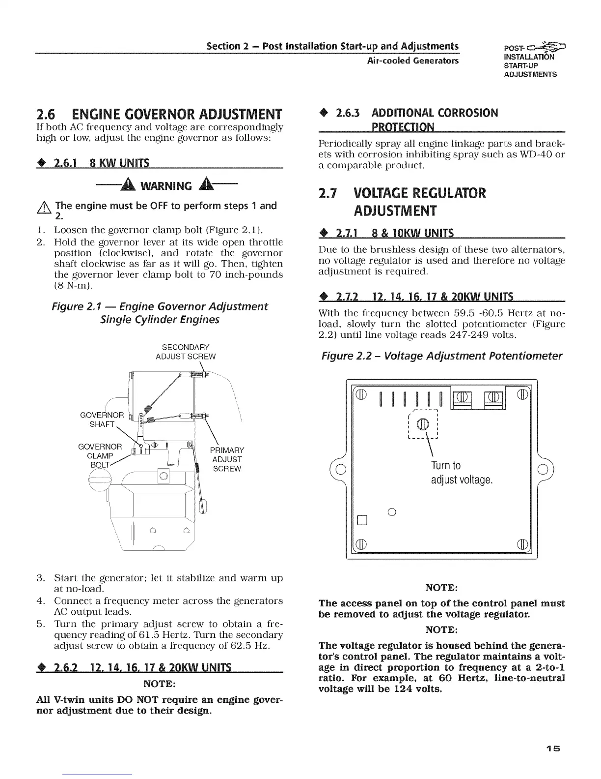
1.
2.
Loosen the governor clamp bolt (Figure 2.1).
Hold the governor lever at its wide open throttle
position (clockwise), and rotate the governor
shaft clockwise as far as it will go. Then, tighten
the governor lever clamp bolt to 70 inch-pounds
(8 N-m).
Figure 2.1 -- Engine Governor Adjustment
Single Cylinder Engines
SECONDARY
ADJUST SCREW
• 2,6,3 ADDiTiONAL CORROSION
PR_
Periodically spray all engine linkage parts and brack-
ets with corrosion inhibiting spray such as WD-40 or
a comparable product.
2.7 VOLTAGEREGULATOR
ADJUSTMENT
2.7,] 1 KW NiT
Due to the brushless design of these two alternators,
no voltage regulator is used and therefore no voltage
adjustment is required.
2.7.2 ]2 14 ] 17 2 KW NiT
With the frequency between 59.5 -60.5 Hertz at no-
load, slowly turn the slotted potentiometer (Figure
2.2) until line voltage reads 247-249 volts.
Figure 2.2 - Voltage Adjustment Potentiometer
f"_ _'_
, /-o-_ \ /
i
[---_J
Turnto
adjust voltage.
O
[]
.@ Q
3. Start the generator; let it stabilize and warm up
at no-load.
4. Connect a frequency meter across the generators
AC output leads.
5. Turn the primary adjust screw to obtain a fre-
quency reading of 61.5 Hertz. Turn the secondary
adjust screw to obtain a frequency of 62.5 Hz.
2..2 ]2 14 ] ]7 2 KW NiT
NOTE:
All V-twin units DO NOT require an engine gover-
nor adjustment due to their design,
NOTE:
The access panel on top of the control panel must
be removed to adjust the voltage regulator.
NOTE:
The voltage regulator is housed behind the genera-
tot's control panel. The regulator maintains a volt-
age in direct proportion to frequency at a 2-to-I
ratio. For example, at 60 Hertz, line-to-neutral
voltage will be 124 volts.
15