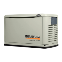
OPERATION
Section 3 - Operation
Air-cooled Generators
-A A.
/_ Do not attempt to activate the transfer switch
manually until all power voltage supplies to the
switch have been positively turned off. Failure
to turn off all power voltage supplies may result
in extremely hazardous and possibly fatal elec-
trical shock.
5. Use the manual transfer handle inside the trans-
fer switch to move the main contacts back to their
UTILITY position, i.e., loads connected to the util-
ity power source (Figure 3.2).
6. Turn ON the utility power supply to the transfer
switch using the means provided.
7. Set the system to automatic operation as outlined
in Automatic Transfer Operation section.
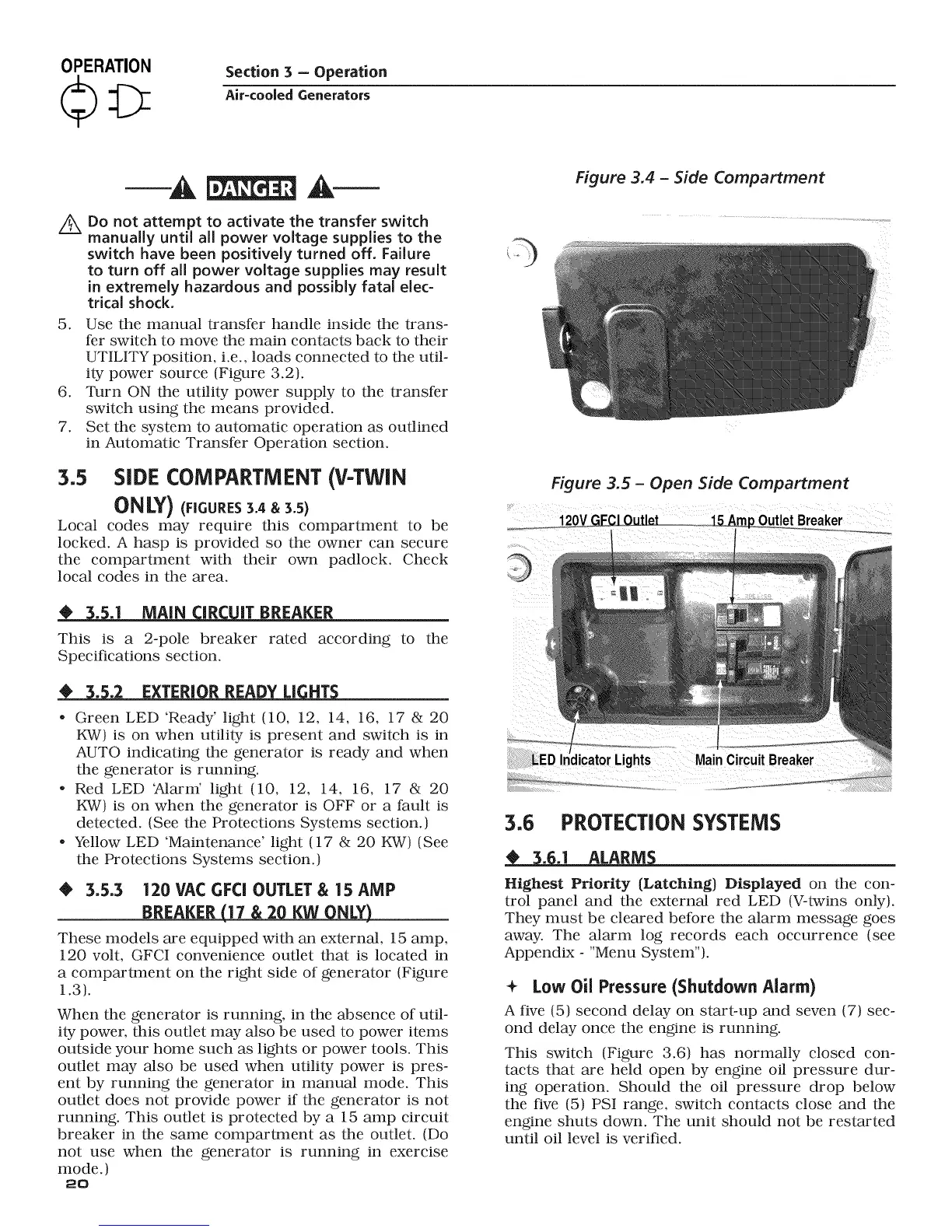
3.5 SIDE COMPARTMENT (V-TWIN
ONLY) (nCURES3.4&3.s)
Local codes may require this compartment to be
locked. A hasp is provided so the owner can secure
the compartment with their own padlock. Check
local codes in the area.
____,3_..1 MAiN IR IT BREAKER
This is a 2-pole breaker rated according to the
Specifications section.
EXTERIOR READY LI NT
. Green LED 'Ready' light (10, 12, 14, 16, 17 & 20
KW) is on when utility is present and switch is in
AUTO indicating the generator is ready and when
the generator is running.
. Red LED 7klarm' light (10, 12, 14, 16, 17 & 20
KW) is on when the generator is OFF or a fault is
detected. (See the Protections Systems section.)
. Yellow LED 'Maintenance' light (17 & 20 KW) (See
the Protections Systems section.)
@ 3.5.3 120 VAC GFCI OUTLET & 15 AMP
BREAKER (17 & 20 KW ONLY)
These models are equipped with an external, 15 amp,
120 volt, GFCI convenience outlet that is located in
a compartment on the right side of generator (Figure
1.3).
When the generator is running, in the absence of util-
ity power, this outlet may also be used to power items
outside your home such as lights or power tools. This
outlet may also be used when utility power is pres-
ent by running the generator in manual mode. This
outlet does not provide power if the generator is not
running. This outlet is protected by a 15 amp circuit
breaker in the same compartment as the outlet. (Do
not use when the generator is running in exercise
mode.)
2o
Figure 3.4 - Side Compartment
Figure 3.5- Open Side Compartment
_.o_._o_ 120VGECL0utlet_.
3.6 PROTECTION SYSTEMS
ALARM_
Highest Priority {Latching) Displayed on the con-
trol panel and the external red LED (V-twins only).
They must be cleared before the alarm message goes
away. The alarm log records each occurrence (see
Appendix - "Menu System").
+ Low Oil Pressure (Shutdown Alarm)
A five (5) second delay on start-up and seven (7) sec-
ond delay once the engine is running.
This switch (Figure 3.6) has normally closed con-
tacts that are held open by engine oil pressure dur-
ing operation. Should the oil pressure drop below
the five (5) PSI range, switch contacts close and the
engine shuts down. The unit should not be restarted
until oil level is verified.