" GENERAL "
INFORMATON
Section | - General information
Air-cooled Generators
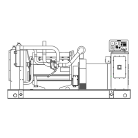
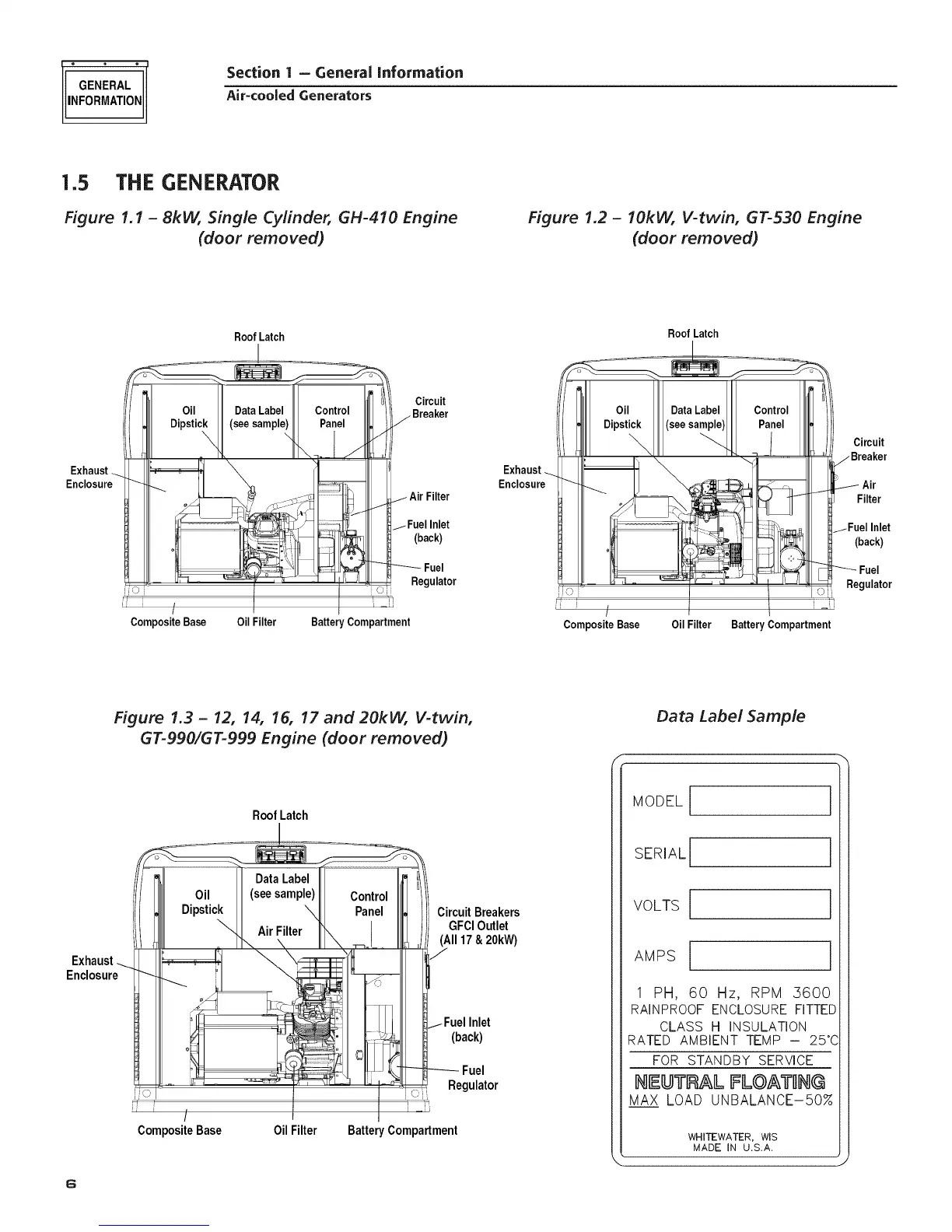
1.5 THE GENERATOR
Figure 1.1 - 8kW, Single Cylinder, GH-410 Engine
(door removed)
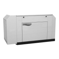
Figure 1.2 - IOkVV, V-twin, GT-530 Engine
(door removed)
Exhaust -_.
Enclosure
Roof Latch
L
'b
Jio i
Oil
Dipstick
\
Data Label Control
(see sample) Panel
\
\- J
I
Oil Filter
Circuit
J _ Breaker
2 iI !
j Air Filter
I Fuel Inlet
(back)
Fuel
Regulator
Composite Base Battery Compartment
Exhaust .__
Enclosure
Roof Latch
Oil Data Label Control _F
Dipstick (see sample) Panel
Composite Base Oil Filter Battery Compartment
Circuit
jBreaker
_i- Air
Filter
1Fuel Inlet
(back)
Fuel
Regulator
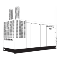
Figure 1.3- 12, 14, 16, 17 and 20kW, V-twin,
GT-990/GT-999 Engine (door removed)
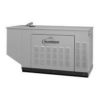
Data Label Sample
Exhaust
Enclosure
6
RoofLatch
1
: j
/
CompositeBase
OilFilter
1_
C
CircuitBreakers
GFClOutlet
(All17&20kW)
/
j-Fuel Inlet
(back)
_ Fuel
Regulator
Battery Compartment
MODEL
SERIAL
VOLTS
AMPS
1
1 PH, 60 Hz, RPM ,3600
RAINPROOF ENCLOSURE FITTEE
CLASS H INSULATION
RATED AMBIENT TEMP - 25°(
FOR STANDBY SERVICE
IItI!UTR_L FLQ_TINQ
MAX LOAD UNBALANCE-50%
WHITEWATER, WIS
MADE IN U,S.A,