9
10. Turn ON the STANDBY (EMERGENCY) power supply to the
transfer switch by whatever means provided (such as the
main line circuit breaker).
11. With the generator running, check that the STANDBY -
OPERATING LED on the switch enclosure door is ON.
12. With an accurate AC voltmeter, check phase-to phase (line-
to-line) and phase-to neutral (line-to neutral) voltages present
at transfer mechanism terminals E1, E2 and E3. Also check
AC frequency at those terminals. Generator AC output voltage
and frequency must be compatible with transfer switch rated
voltage and frequency.
DANGER
Ensure that the phase rotation of STANDBY
(GENERATOR) power lines and transfer switch
NORMAL (UTILITY) and load power lines are
compatible.
13. If supplied voltage or frequency is incorrect, refer to standby
generator Owner’s Manual. If AC frequency is incorrect,
adjust engine governed speed. If voltage is incorrect, adjust
generator’s voltage regulator or correct the problem.
14. When supplied voltage and frequency is correct, shut down
the engine manually.
DANGER
Supplied voltages from both NORMAL (UTILITY)
and STANDBY (EMERGENCY) power sources
must be compatible with transfer switch rated
voltage before proceeding.
15. Connect the transfer switch load to the transfer switch when
“voltage checks” section has been completed. Connect the
load to the transfer switch by whatever means provided (such
as circuit breaker(s)), then proceed with the “ELECTRICAL
OPERATION” section.
3.4 ELECTRICAL OPERATION
Test transfer system electrical operation as follows:
1. On the enclosure door, check that the UTILITY AVAILABLE
LED is ON.
2. On the enclosure door, check that the SWITCH POSITION-
UTILITY LED is ON.
The UTILITY AVAILABLE LED and the SWITCH
POSITION-UTILITY LED (on enclosure door)
must both be ON before proceeding to Step 3.
3. Refer to the appropriate owner’s manual. Be sure the standby
generator is prepared for automatic operation.
4. In the switch enclosure, set the Maintenance Disconnect
switch to AUTOMATIC.
5. Press the “TEST” button on the enclosure door. Generator
startup and transfer to the STANDBY power source should
occur. Refer to the “Sequence of Operation” section.
6. Press the “TEST” button again to initiate the retransfer
sequence. The customer LOAD will be transferred back to the
UTILITY power source, using the preset times. The generator
will shut down once the engine cool down timer has expired.
3.5 TRANSFER MECHANISM
The transfer mechanism houses the main, current carrying con-
tacts, along with other mechanical and electrical components,
required for operating the switch. The main contacts are electri-
cally operated and mechanically latched in place.
Power for the closing, selective and trip coil is taken from the
source of supply that the Customer Load is being transferred to.
Therefore, transfer to any power source cannot occur unless that
power source is available to the switch.
Customer Load contacts are bolted to an insulated plastic pole
piece and are stationary. The UTILITY (NORMAL) and GENERATOR
(EMERGENCY) contacts are moveable.
3.6 TRANSFER MECHANISM
OPERATION
There are three (3) coils inside a "WN" switch that are used in
transferring power to the respective load;
Closing Coil - When energized, closes the main contacts on •
Utility or Generator side, depending on if the select coil is
energized or not.
Select Coil - When energized, the mechanism is configured to •
close the Generator supply contacts when the closing coil is
energized.
Trip Coil - When energized, the main contact latch is released •
and the contacts move to the open position by spring tension.
All 3 solenoids are only energized momentarily.
Refer to the diagnostic repair manual 079247, section 9.6 for
complete operational analysis.
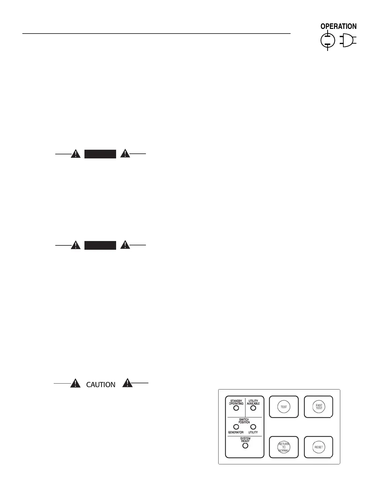
3.7 SWITCHES AND INDICATORS
This section will familiarize the reader with switches and indicators
on the membrane switch panel mounted on the enclosure door,
as well as the Maintenance Disconnect switch inside the switch
enclosure. See Figure 3.2.
Figure 3.2 — OTTS Switch
Section 3 — Operation
HTS “Wn” Type Transfer Switch

 Loading...