12
Section 3 — Operation
HTS “Wn” Type Transfer Switch
3.8.10 SEQUENCE 10 - ENGINE COOLDOWN TIMER
Engine Cooldown timer starts The Engine Cooldown timer can •
be set from 0 to 1,200 seconds. Factory default setting varies
depending on the engine used.
The engine generator will shutdown when the Engine Cooldown •
timer and the Engine Minimum Run timer expires.
NOTE:
At the conclusion of sequence 10 the system is armed and
ready for the next Utility failure or exercise sequence.
3.9 TRANSFER SWITCH OPTIONS
The transfer switch may be equipped with one or more of the fol-
lowing options:
Instrument Package, 3.11.2•
Signal Before Transfer, 3.11.1•
NEMA 3R, 4, 4X or 12 enclosure•
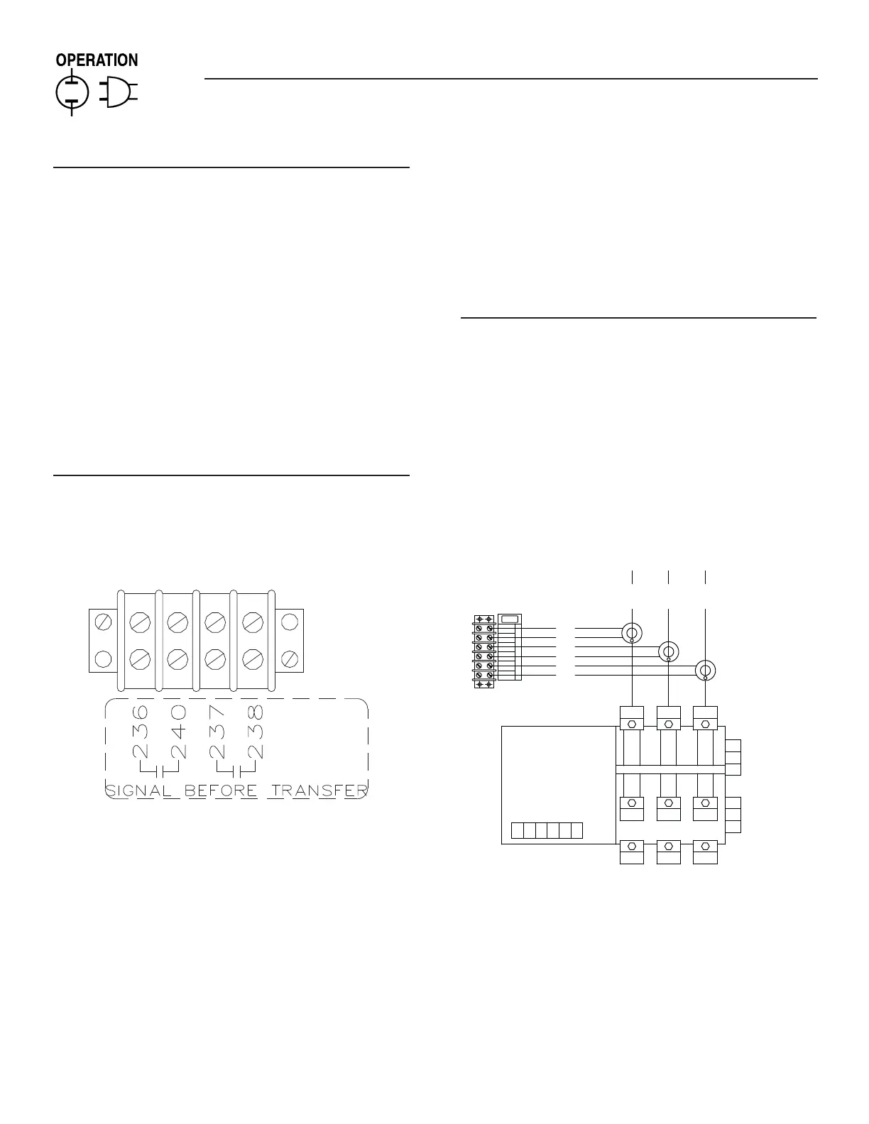
3.9.1 SIGNAL BEFORE TRANSFER
The Signal Before Transfer option includes a signal relay, customer
connection terminal strip and the associated wiring. See Figure
3.3.
Figure 3.3 — Signal Before Transfer
The logic for this option is a part of the G/H-panel controller. The
delay time is adjustable from 0 to 30 seconds. Set the timer to “0”
when this option is not desired.
The basic operation of the option is to delay (for the period of
time set) the transfer of the GTS mechanism while a signal relay
(SR) is energized. When the relay is energized, two sets of the dry
contacts (wires 236 and 240, and 237 and 238) are closed. These
dry contacts can be connected to, via a terminal strip located on
the bottom of the subplate. Reference wiring diagram 0F5520 or
0F5036 for further details. The customer connections are made on
terminal strip TB3-1.
NOTE:
This delay is not active on a Normal source failure. Transfer
during Normal source failure is immediate.
NOTE:
The “Signal Before Transfer” feature provides a time delay
that allows elevators to continue operating before transfer to
another power supply occurs.
3.9.2 INSTRUMENT PACKAGE
This option is used to measure the Utility source current that is
coming to the transfer switch. The instrument package includes
a terminal strip used to connect the current transformers and
associated wiring. The HTS controller takes in the current signals
and passes them on to the Hxxx or Gxxx panel for display on a PC
through GenLink-DCP.
Route the Utility Supply cables through the center of the current
transformers. Connect the signal wires of the current transformers
to terminal strip (TB1-1). See Figure 3.8 for three-phase connec-
tion details. See Figure 3.9 for single-phase connection details.
Figure 3.8 — Connect Signal Wires
(Three-phase)
AT S
AUX
(BLK)
(WHT)
(BLK)
(WHT)
(BLK)
(WHT)
CT CONNECTION
P/N 0F5039
PH "A"
PH "A"
PH "B"
PH "B"
PH "C"
PH "C"
TB1
A1
B2
A2
B1
T2
T1
ATS-X
T1
E1
T2
E2
ATS-Y
N1 N2
AT S- Z
T3
E3
COM
NO
NC
COM
NO
N3
NC
46357-T
WHT
BLK
BLK
WHT
WHT
BLK
PH "A"
PH "C"
PH "B"
NOTE: WHITE DOT ON CT
TO FACE AWAY FROM
TRANSFER SWITCH

 Loading...