4
NOTE:
It is essential to use the latest version of any standard to ensure
correct and current information.
2.1 INTRODUCTION TO
INSTALLATION
This equipment has been wired and tested at the factory. Installing
the switch includes the following procedures:
Mounting the enclosure.•
Connecting power source and load leads.•
Connecting the generator communication circuit.•
Setting DIP switches on ATS controller.•
Programming Gxxx or Hxxx control on engine generator.•
Installing/connecting any options and accessories.•
Testing functions.•
2.2 UNPACKING
Carefully unpack the transfer switch. Inspect closely for any dam-
age that might have occurred during shipment. The purchaser
must file with the carrier any claims for loss or damage incurred
while in transit.
Check that all packing material is completely removed from the
switch prior to installation.
Attach any lifting device to the transfer switch mounting holes or
brackets only. DO NOT LIFT THE SWITCH AT ANY OTHER POINT.
2.3 MOUNTING
Mounting dimensions for the transfer switch enclosure are in this
manual. Enclosures are typically floor standing and mounted to
the wall. Components are generally mounted in a standard NEMA
12-type enclosure. A NEMA 3R, is also available. See TRANSFER
SWITCH OPTIONS section.
Handle transfer switches carefully when install-
ing. Do not drop the switch. Protect the switch
against impact at all times, and against con-
struction grit and metal chips. Never install a
transfer switch that has been damaged.
Install the transfer switch as close as possible to the electrical
loads that are to be connected to it. Stand the enclosure on a flat
surface. If the surface is not flat, it will be necessary to add shims
to make the enclosure level. Mount to a wall or support structure
for vertical stability. To prevent switch distortion, level all mounting
points. If necessary, use washers behind mounting holes to level
the unit.
2.4 CONNECTING POWER SOURCE
AND LOAD LINES
DANGER
Make sure to turn OFF both the NORMAL
(UTILITY) and STANDBY (EMERGENCY) power
supplies before trying to connect power source
and load lines to the transfer switch. Supply
voltages are extremely high and dangerous.
Contact with such high voltage power supply
lines causes extremely hazardous, possibly
lethal, electrical shock.
Wiring diagrams and electrical schematics are provided in this
manual. Power source and load connections are made at a transfer
mechanism, inside the switch enclosure.
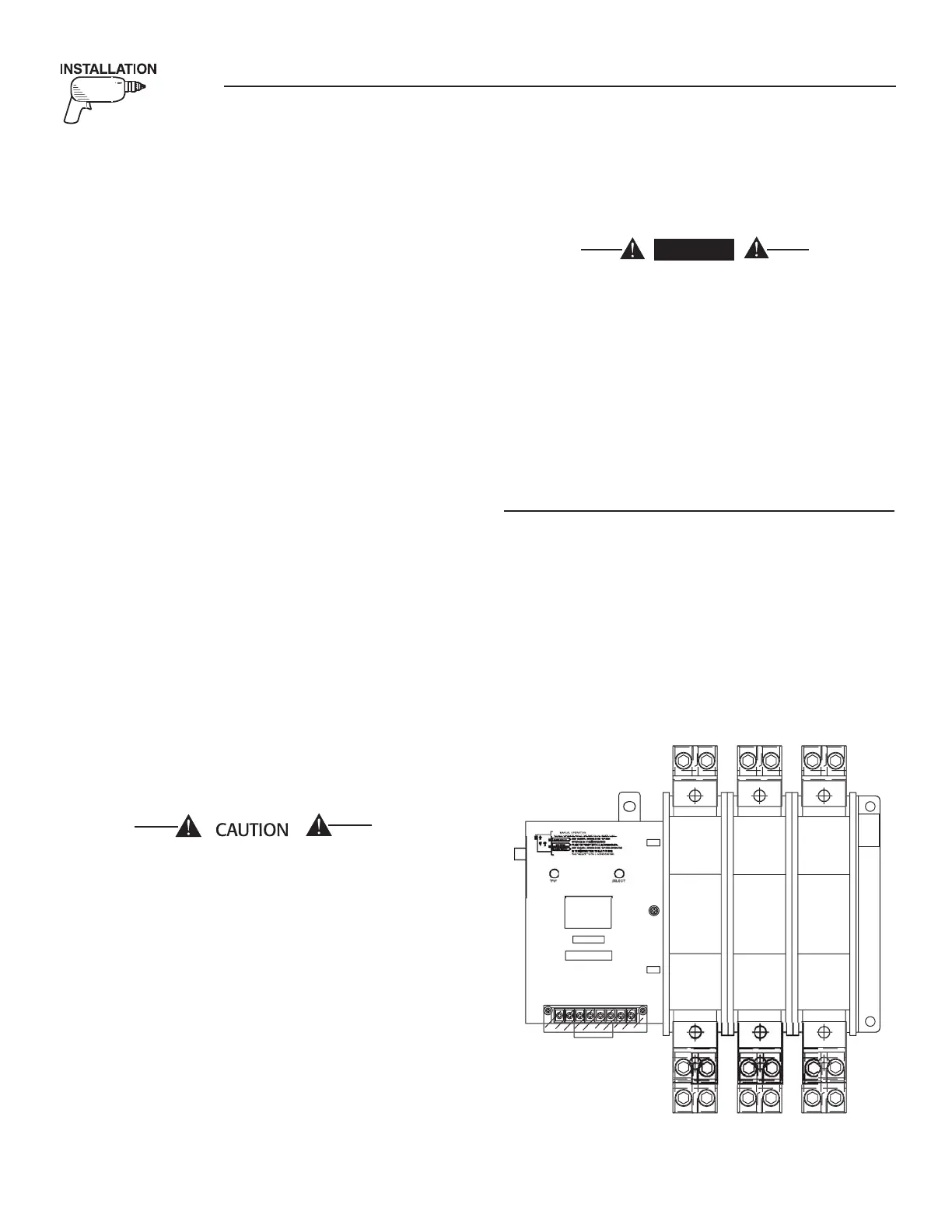
2.4.1 TRANSFER MECHANISMS
The transfer mechanism may be either a 2-pole, 3-pole, or 4-pole
type (Figure 2.1). The switch enclosure may include a NEUTRAL
BLOCK for connection of the NEUTRAL line. Connect power source
and load leads to transfer mechanism terminal lugs as follows:
LOAD Leads: Connect to terminals T1, T2, T3, etc.•
NORMAL (• UTILITY) Source Leads: To terminals N1, N2, N3,
etc.
STANDBY (• EMERGENCY) Source Leads: Connect to transfer
mechanism terminal lugs E1, E2, E3, etc.
Figure 2.1 — Transfer Mechanism
TILIT
TANDB
F
47
VA
TRAN
FER
WIT
RATED
RREN
4
VA
RATED V
LTA
4
AM
27
7-T
27
7-T
27
7-T
062707-
062707-
062707-
Section 2 — Installation
HTS “Wn” Type Transfer Switch

 Loading...