7
3.1 FUNCTIONAL TESTS AND
ADJUSTMENTS
Following transfer switch installation and interconnection, inspect
the entire installation carefully. A competent, qualified electrician
should inspect it. The installation should comply strictly with all
applicable codes, standards, and regulations. When absolutely
certain the installation is proper and correct, complete a functional
test of the system. Perform functional tests in the exact order pre-
sented in this manual, or the switch could be damaged.
IMPORTANT: Before proceeding with functional tests, read and
make sure all instructions and information in this section are
understood. Also read the information and instructions of labels
and decals affixed to the switch. Note any options or accessories
that might be installed and review their operation.
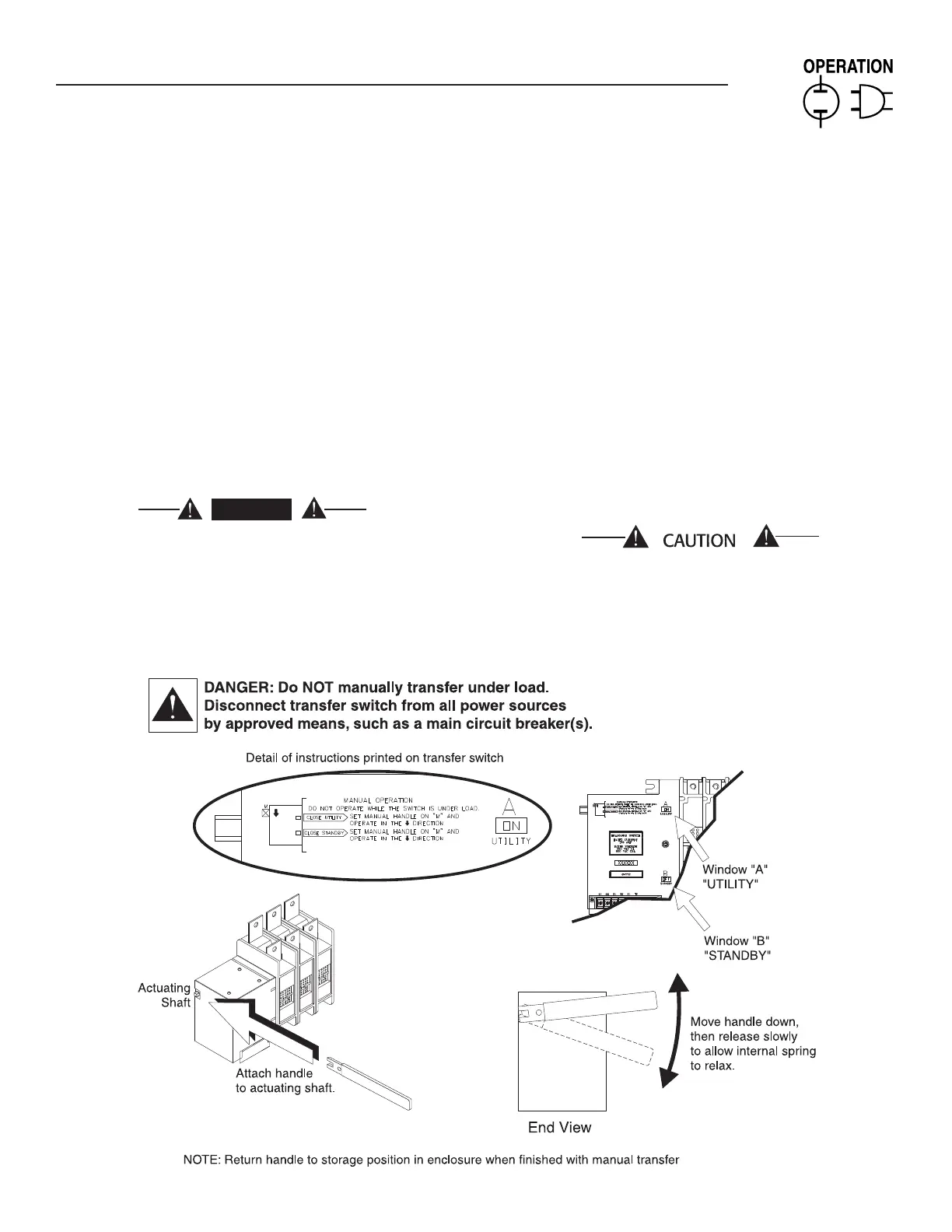
3.2 MANUAL OPERATION
DANGER
Do NOT manually transfer under load.
Disconnect transfer switch from all power sourc-
es by approved means, such as a main circuit
breaker(s).
A manual HANDLE is shipped with the transfer switch. Manual
operation must be checked BEFORE the transfer switch is operated
electrically. To check manual operation, proceed as follows:
1. In the transfer switch enclosure, set the Maintenance
Disconnect switch to MANUAL. This prevents the generator
from starting automatically as soon as the UTILITY power
source is turn OFF.
2. If so equipped, turn the generator’s AUTO/OFF/ MANUAL
switch to OFF.
3. Turn OFF both NORMAL and STANDBY power supplies to the
transfer switch, with whatever means provided (such as the
main line circuit breaker(s)).
4. Note position of transfer mechanism main contacts by
observing display windows in “A” and “B” in Figure 3.1 as
follows:
Window “A” ON, Window “B” OFF - LOAD terminals (T1, T2, •
T3) are connected to NORMAL terminals (N1, N2, N3).
Window “A” OFF, Window “B” ON - LOAD terminals (T1, T2, •
T3) are connected to STANDBY terminals (E1, E2, E3).
Do not use excessive force when operating the
transfer switch manually or the manual handle
could be damaged.
Section 3 — Operation
HTS “Wn” Type Transfer Switch
Figure 3.1 — Actuating Transfer Switch

 Loading...