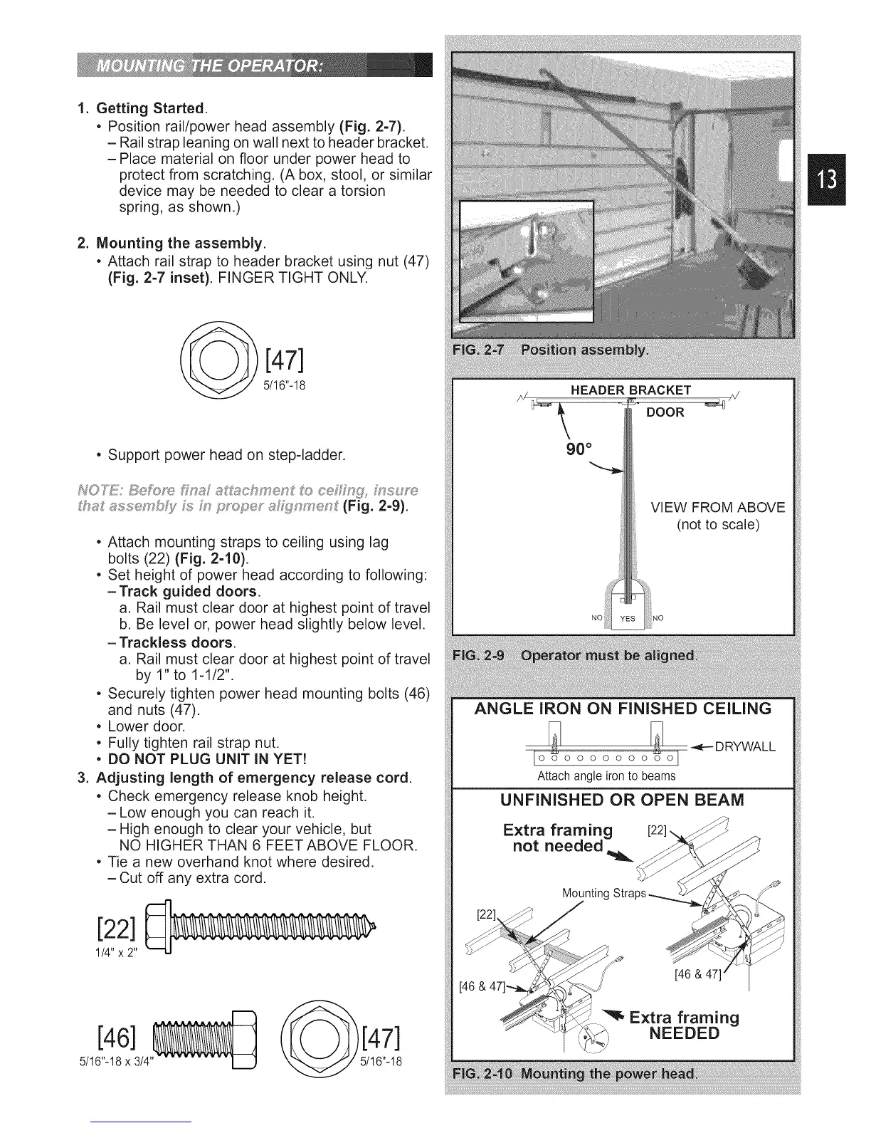
1. GettingStarted.
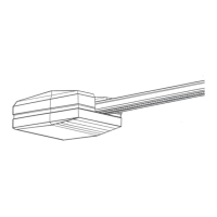
• Positionrail/powerheadassembly(Fig.2-7).
- Railstrapleaningonwallnexttoheaderbracket.
-Place materialonfloorunderpowerheadto
protectfromscratching.(Abox,stool,orsimilar
devicemaybeneededtocleara torsion
spring,asshown.)
2, Mountingthe assembly.
• Attachrail straptoheaderbracketusingnut(47)
(Fig.2-7inset).FINGERTIGHTONLY.
[47]
5/16"-18
• Support power head on step-ladder.
NO}_1Y Beh:_ye £_a,_ s SxJ_ch£en {to ceh£ng, msu_'e
tha£ asse _,Ls,_}/h m phspe_ a_V{i_n_'en£(Fig. 2-9).
• Attach mounting straps to ceiling using lag
bolts (22) (Fig. 2-10).
• Set height of power head according to following:
- Track guided doors.
a. Rail must clear door at highest point of travel
b. Be level or, power head slightly below level.
- Trackless doors.
a. Rail must clear door at highest point of travel
by 1" to 1-1/2".
• Securely tighten power head mounting bolts (46)
and nuts (47).
• Lower door.
• Fully tighten rail strap nut.
• DO NOT PLUG UNIT IN YET!
3. Adjusting length of emergency release cord.
• Check emergency release knob height.
-Low enough you can reach it.
-High enough to clear your vehicle, but
NO HIGHER THAN 6 FEET ABOVE FLOOR.
• Tie a new overhand knot where desired.
-Cut off any extra cord.
[22]
I/4" x2"
[46]
5/16"-18x 3/4
J
HEADER BRACKET
DOOR
90 °
VIEW FROM ABOVE
(not to scale)
ANGLE IRON ON FINISHED CEILING
_ _ DRYWALL
[o ooooooo oj
Attach angle iron to beams
UNFINISHED OR OPEN BEAM
Extra framing
not needed
Mounting
[46 &
[46 &
_, Extra framing
NEEDED
 Loading...