Sec-3.14
Section 3: Wiring
Blue
Orange
Yellow
External Radio Harness
NOM
+24 VDC
Relay GND
Blue
Orange
Yellow
External Radio Harness
NOM
+24 VDC
Relay GND
3 Wire Radio
FIG. 8
-
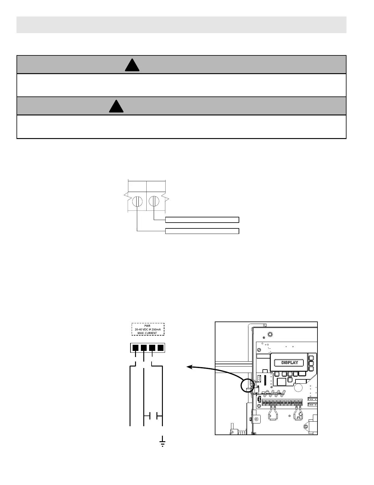
HIGH VOLTAGE
INPUT PLUG
LINE INPUT
TERMINALS
LINE
GROUND
ROUTE LINE VOLTAGE
WIRING IN SHADED
AREA AS SHOWN
L1
N
GND
LINE IN
120V
LINE
(HOT)
NEUTRAL
HIGH VOLTAGE
INPUT PLUG
POWER CONNECTIONS
Non-Monitored Safety Edge:
Actuating the operator by using constant contact on the CLOSE button will override non-functioning
external reversing devices, including sensing edges.
WARNING
AVERTISSEMENT
L’activation de l’operateur en util isant un contact constant sur le bouton FERMER annulera les dispositifs
d’inversions externes, y compris les systèmes de détection des bords.
1. Make wire connections to external radio harness (provided) as shown.
2. Install harness to external radio harness plug on control board as shown.
Installing external radio for remote operation. FIG. 8.
External Radio Installation (Optional):
NOTE: A monitored safety device must be used when installing an external radio for remote operation. Operator
controls must be set for momentary contact for remote operation.
1. Route wires into operator electric box using suitable conduit and clamp systems.
2. Attach wires to N-O SAFETY terminals on control wire terminal strip.
N-O
SAFETY
N-O
SAFETY
TERMINAL STRIP
Non-Monitored
Safety Edge
 Loading...