BRAIN 17 10 732788 - Rev. A_1
햲
헁
FCC2
FCC1
FCA2
FCA1
22 23 24 25
J6
J6
햳
FCC2
FCC1
FCA2
FC
A1
22 23 24 25
J6
TIMECODER 2
TIMECODER 1
헁
헁
헄
헄
J6
FC
C2
FCC1
FCA2
FC
A1
22 23 24 25
J6
헁
헁
헄
헄
TIMECODER 2
TIMECODER 1
J6
햴
ENGLISH
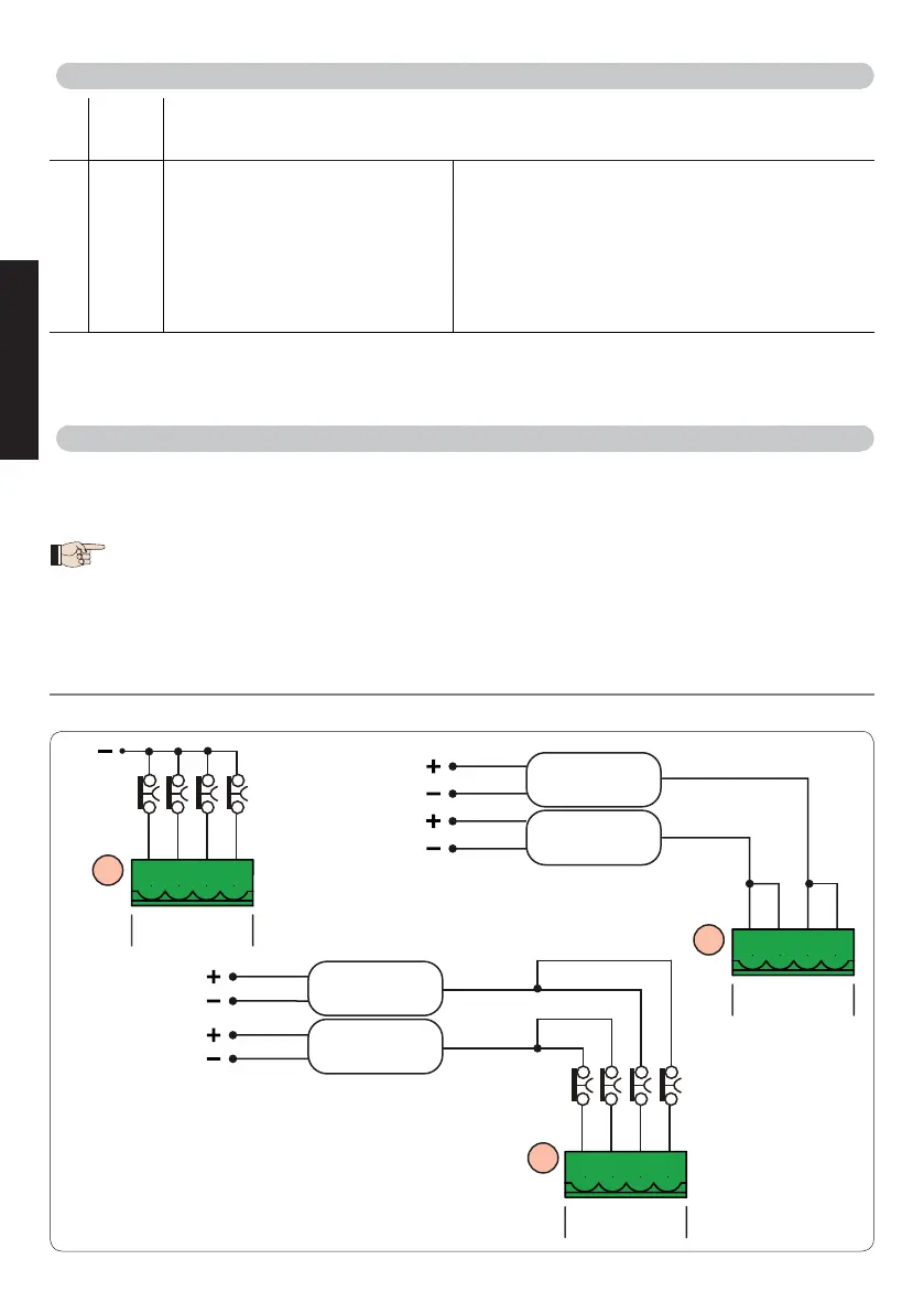
FCA1, FCC1 and TIMECODER1 correspond to LEAF 1;
FCA2, FCC2 and TIMECODER2 correspond to LEAF 2.
4.4 J12 - PROGRAMMABLE OUTPUTS - ELECTRIC LOCKS
20 W.L.
24 V
"
(Open Collector) programmable using the function
SP
(advanced programming);
default: indicator light
21 LOCK
Electric lock (12 V~ or 24 V
"
)
operated 2 sec before opening
of leaf 1
When BUS G-WAY encoder is disabled, the electric
lock is operated before each opening (in whatever
position the stopped leaf is in).
When BUS G-WAY encoder is enabled, the electric
lock is operated only before opening the closed leaf.
4.5 J12 -J6 - LIMIT SWITCH AND TIMECODER
The limit switch contacts FCC1, FCA1, FCC2, FCA2 are all NC contacts.
They are programmable using the functions
FA
and
FC
(basic programming) ; default: disabled.
If no limit switches are used, you DO NOT need to jumper the limit switch contacts
FCC1, FCA1, FCC2, FCA2.
You can however use a single TIMECODER (only for single leaf); in this case, you do
not need to jumper the unused inputs to the earth.
Fig. Limit switch and TIMECODER connections (maximum configuration:
햴
).