BRAIN 17 27 732788 - Rev. A_1
ENGLISH
5.3 BUS G-WAY DEVICE INSTALLATION
You can add BUS G-WAY devices to the system at any time, proceeding as follows:
1. Cut off the electrical power to the board.
2. Install and set the BUS G-WAY accessories according to the instructions of the devices.
3. Connect the BUS G-WAY devices according to the instructions of Chapter ELECTRICAL CONNECTIONS.
4. Power up the board.
5. Complete the procedure for BUS G-WAY device entry.
5.3.1 BUS G-WAY DEVICE ENTRY
1. Access BASIC programming and scroll through the functions up until
bu
. When
is released, the
display will show the BUS G-WAY devices status (see the figure).
2. Perform the entry: simultaneously press and hold
and
-
for at least 5 sec (during this time, the
display will blink).
3.
Y
will appear as a confirmation of entry completion.
4. Release the
and
-
buttons. The status of the BUS G-WAY devices will be displayed.
If no BUS device has ever been entered in the board, the display will read
no
.
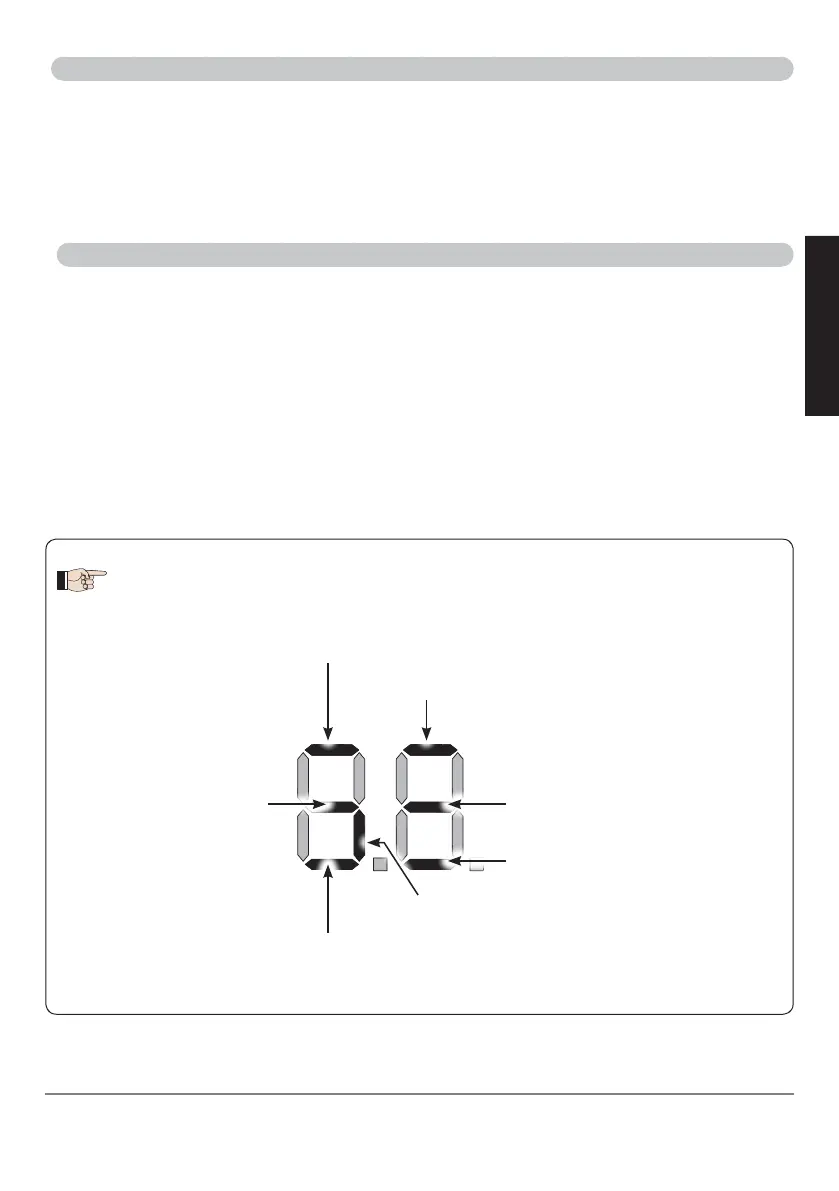
Encoder 1: ON = correctly connected
and entered
Encoder 2:
ON = correctly connected and
entered
BUS Status: always ON
OPEN photocell:
ON = entered and engaged
Opening photocells:
ON = entered and engaged
Closing photocells:
ON = entered and engaged
Fig. Visualising the BUS G-WAY status in the function
bu
: each segment of the display shows one type
of device.
Opening photocells
and Closing photocells:
ON = entered and engaged