BRAIN 17 15 732788 - Rev. A_1
LOCK
STOPOP-A
W.L.
24V
1110
OP-B
2120181716159
LOCK
STOPOP-A 24V
1110
OP-B
2120181716159
TX FSW
19
1412 13
CL FSW OP
9 10 11
12
13
14
15 16 17 18
19
20 21
LOCK
STOPOP-A
W.L.
24V
1110
OP-B
2120181716159
LOCK
STOPOP-A 24V
1110
OP-B
2120181716159
TX FSW
19
1412 13
CL FSW OP
9 10 11
12
13
14
15 16 17 18
19
20 21
ENGLISH
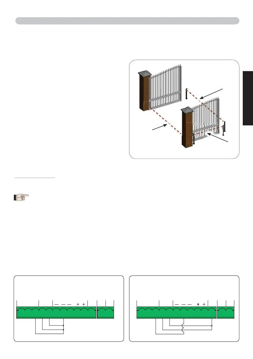
4.8 TRADITIONAL PHOTOCELLS
This board lets you use traditional photocells (contact N.C. with relay).
Before connecting the photocells, it is best to identify the operating type, which depends on the mo-
vement area they have to protect:
Closing photocells:
trip only during the auto-
mated system closing
- suitable for protecting the
closing area from risk of impact.
Opening photocells:
trip only during the auto-
mated system opening
- suitable for protecting the
opening area from risk of impact.
Photocells for opening/closing:
trip during both
the opening and closing
- suitable for protecting the
entire movement area from risk of impact.
Pulse generators: used as pulse generators for
opening the automated system
.
Fail Safe function
This function lets you monitor the correct alignment and operation of the photocells before each move-
ment. To enable the Fail Safe function, enter the ADVANCED Programming and set the
SP
=
01
function.
With Fail Safe disabled: connect the transmitter (TX) power supply to terminals 15 and
18 of J3.
With Fail Safe enabled:
connect the power supply negative of the transmitters (TX) to
TXFSW
.
Then jumper the unused safety inputs with TXFSW.
Hereafter are provided the drawings for some connection examples.
Closing
safety devices
Opening
safety devices
Safety devices for
opening/closing
No safety device and no stop device
FAIL SAFE disabled
No safety device and no stop device
FAIL SAFE enabled