BRAIN 17 28 732788 - Rev. A_1
+/
R1
ENGLISH
In STAND BY (gate closed and in stand-by) with
BUS G-WAY Encoder on leaf 1 and leaf 2 and
BUS G-WAY Photocells correctly connected and
entered.
In case of BUS G-WAY Encoder on leaf1 and leaf 2
and BUS G-WAY Photocells correctly connected and
entered and with closing photocells engaged:
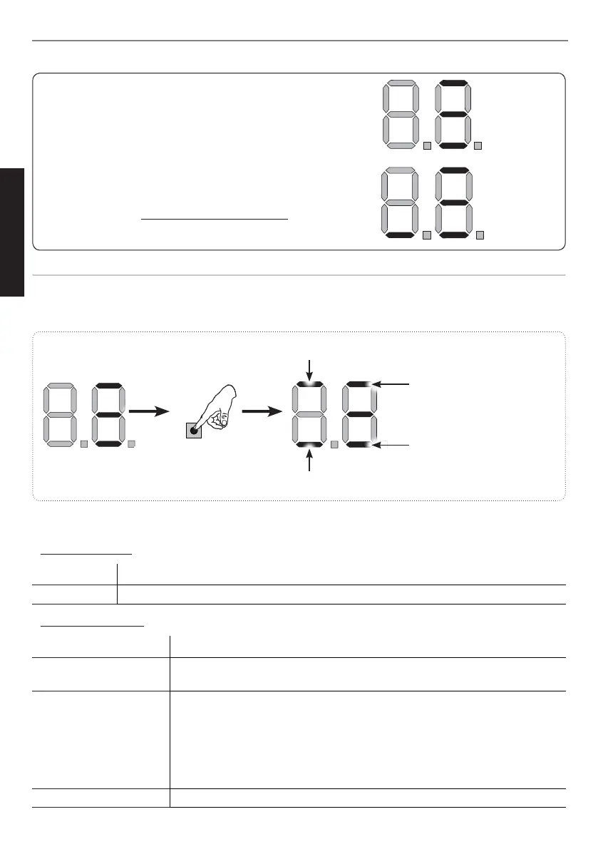
Encoder on leaf 1 correctly
entered
Encoder on leaf 2 correctly
entered
at least one pair of opening
photocells correctly entered
at least one pair of closing
photocells correctly entered
Fig. examples of BUS G-WAY status visualization on display.
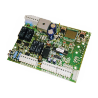
Checking the securing devices entered on the board
To verify the types of BUS device recognised through the entry:
1. Press and hold the
button during stand-by visualisation; the segments corresponding to at least
one entered device will go ON. E.g.:
To check the condition of the BUS G-WAY connection, verify the LED on the board:
LED DL15 (Red)
ON Safety device engaged or pulse generator active
OFF NO safety device engaged neither pulse generator active
LED DL14 (Green)
ON steady Normal activity (led ON even if there are no devices).
Slow blinking (blink
every 2,5 sec)
BUS G-WAY line short-circuit.
Rapid blinking (blink
every 0.5 sec)
Error in the BUS G-WAY connection.
Repeat the device entry. If the error occurs again, check:
- That there are no more than one device in the system with the same
address.
- Calling error (number > or < the connected BUS devices).
- FAIL SAFE error on the BUS device.
OFF Board in Sleep mode (if used).