October 29, 2015
8
3. Accessing the Web Interface of the GV-AS Controllers
After connecting the required wires and cables for the following GV-AS Controllers, access
the Web interface of the GV-AS Controller to define the devices connected: GV-AS1010 /
1110 / 210 / 2110 / 2120 / 410 / 4110 / 810 / 8110 and GV-EV48. The section numbers listed
here refers to the GV-AS Controller User Manual.
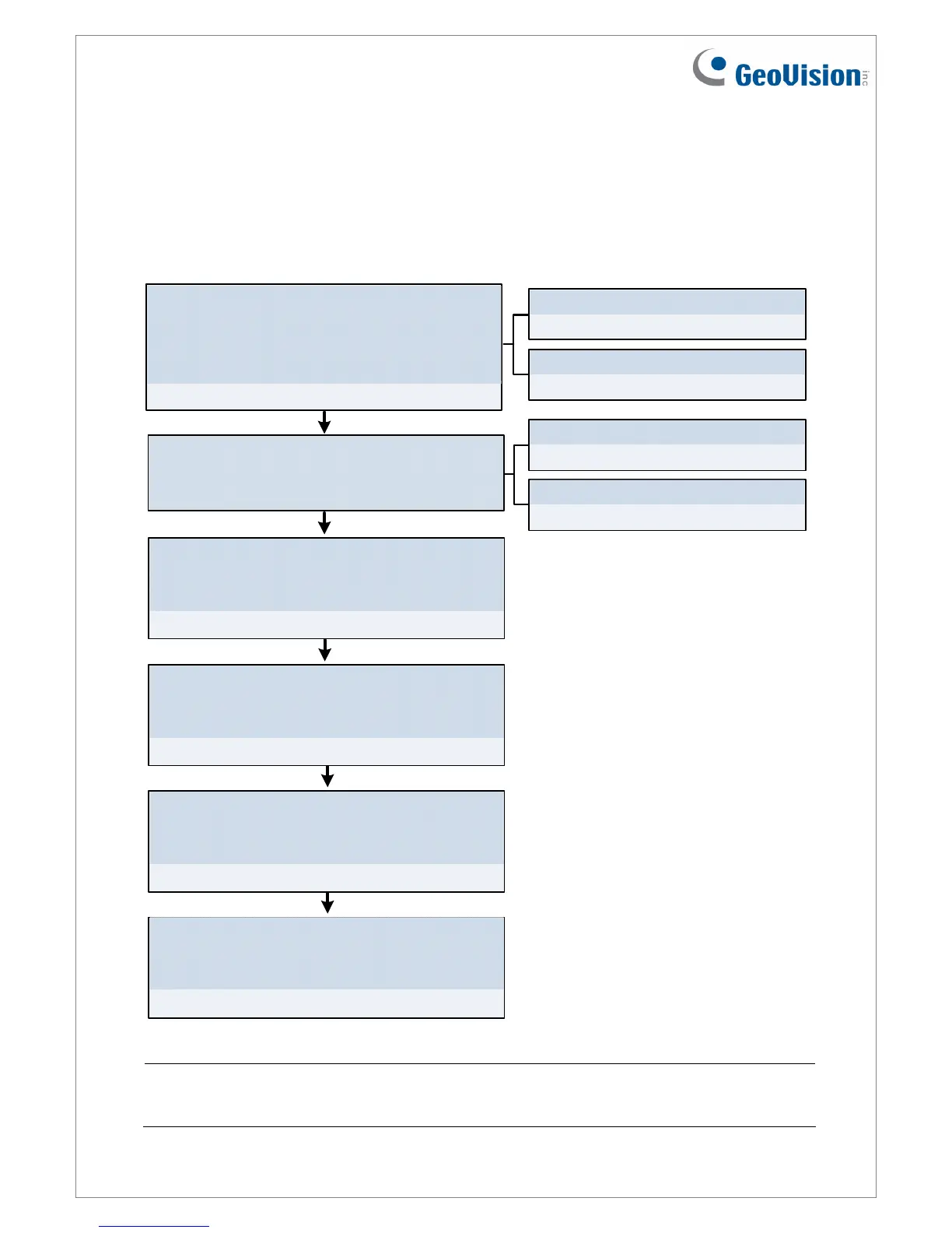
8.2.7 Output Configuration
8.2.6 Input Configuration
8.2.2 Parameter Configuration
8.2.1 Function Configuration
8.3.1 Extended Reader
8.2.8 Wiegand Function
7.2 DHCP Connection
7.1 Fixed IP connection
Chapter 7 Installing on a Network
Set network configurations
Assign a static IP address or set up DDNS to
map a dynamic IP address to a static domain
name.
Set card readers
Define the connected readers by selecting the
corresponding doors / gates.
Set Function Configuration
Specify the function and the authentication
mode for each door / gate.
Static IP address
Dynamic IP address
Set Wiegand readers
Set RS485 or TCP/IP readers
Set Parameter Configuration
Set the door operation for different situations
and enable alarms for each door / gate.
Set Input Configuration
Name the input devices connected and set the
input type and input function.
Set Output Configuration
Name the output devices connected and set the
output type, function and conditions.
Note: The Wiegand Function and Output Settings pages are not available for GV-AS1010 /
1110 and GV-EV48. For GV-EV48, the Input Setting page is also not available.

 Loading...


