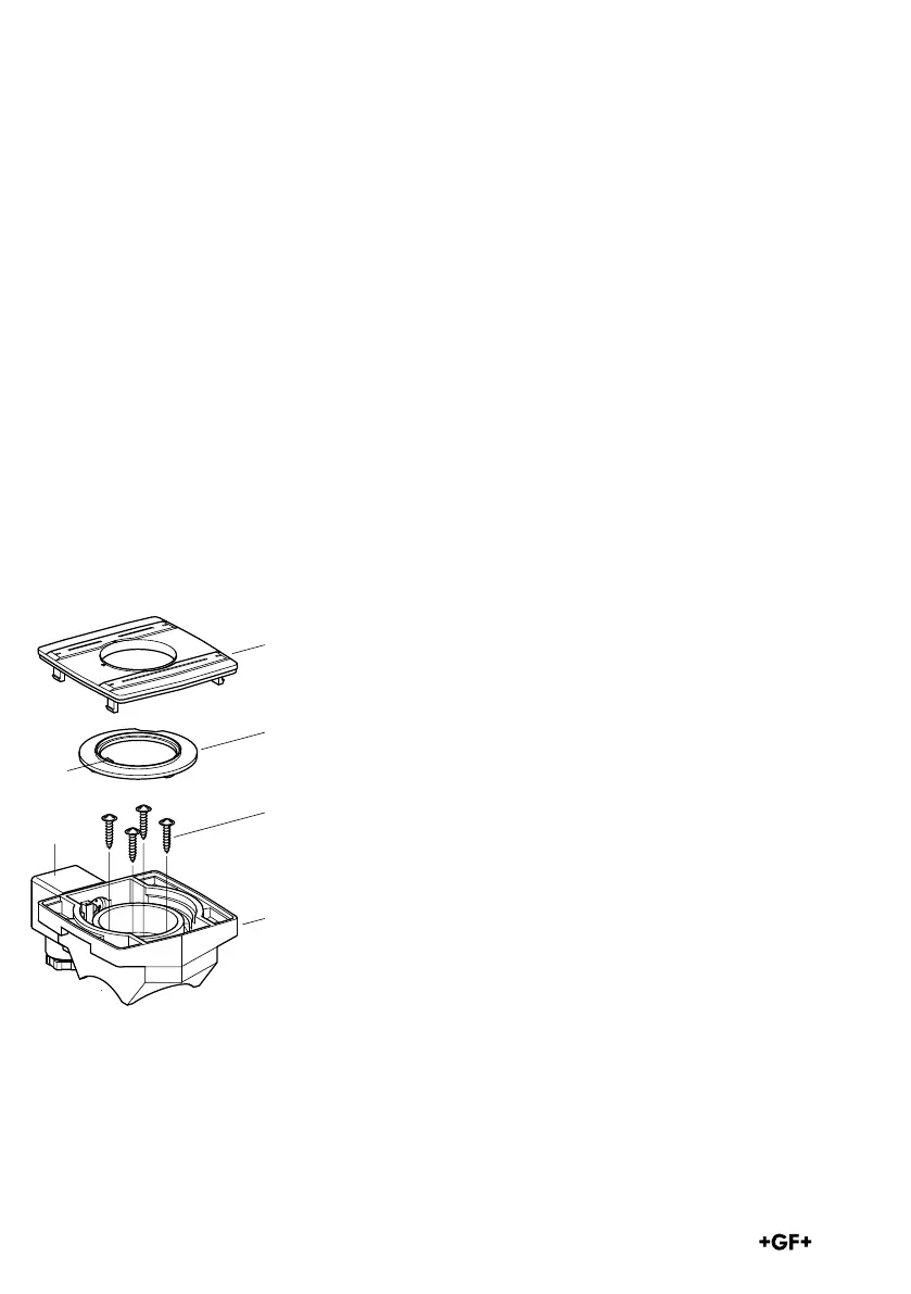
Exploded drawing
1 Housing
2 Housing cover
3 Indexing disk
with switching cams 3a
4 Screws
5 Connector plug 3P + E per DIN EN
¢75301-803
(formerly DIN 43650)
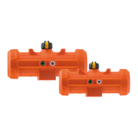
The MF module can be mounted on the ball valve type
546 in the opened or closed ball position.
Spigot is asymmetrical
The spigot position must be identical to one of
the
two illustrations.
10. Installation of the
Multifunctional Module with
Built-in Limit Switch
Prior to installation, inspect the MF module for trans-
port damages. We recommend leaving the MF module
in its original packaging until you are ready to install it.
The MF module has been fitted with the respective swit-
ches and function-tested ex works! It is not necessary
to remove the cover.
Design of the MF- module with built-in switch