Fitting together with an alr
eady fitted service unit of the
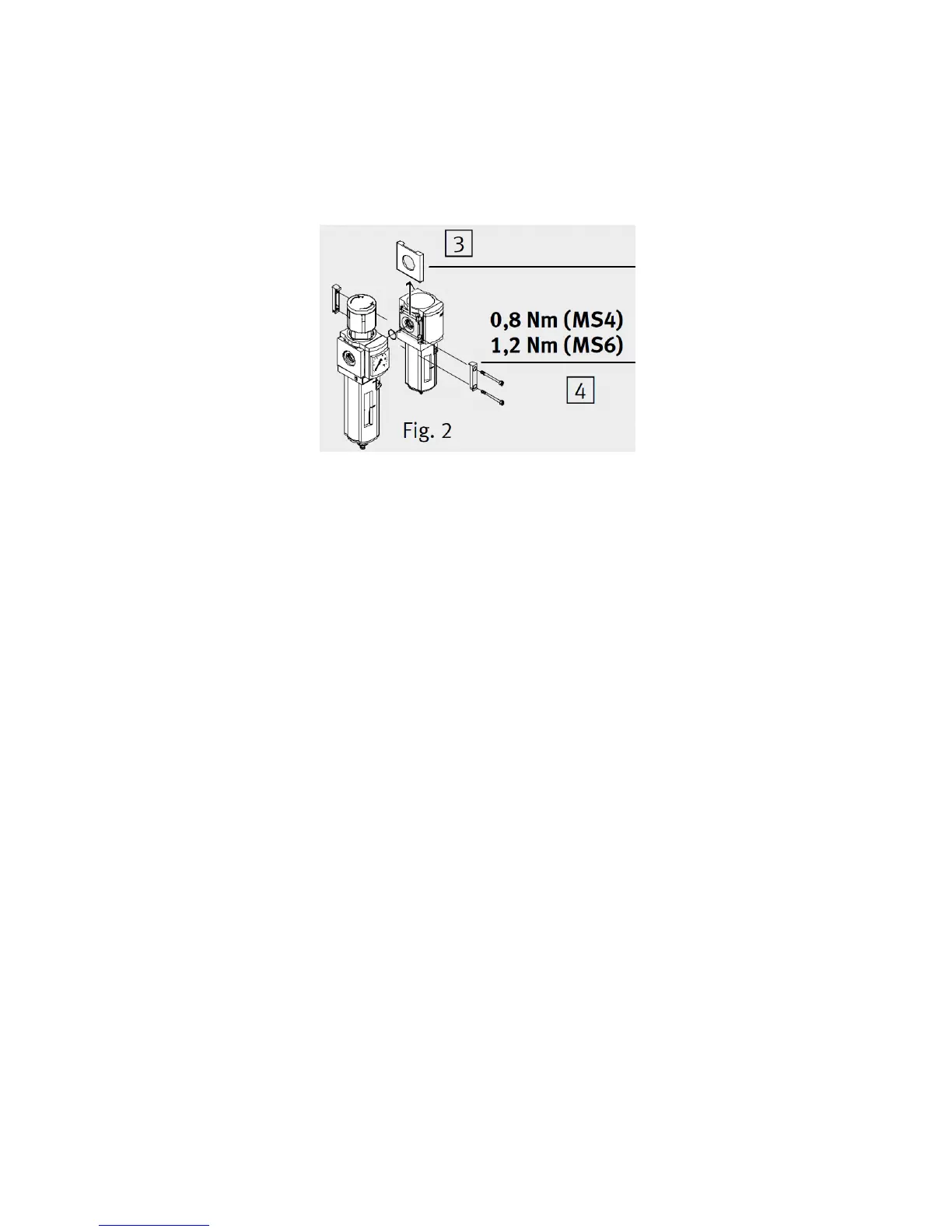
.Remove the cover plates3on the sides to be fitted together (push upwards).
.Place the module connectors MS4/6-MV4 in the
grooves of the individual units. There must be
seal between the individual units.
. Insert two screws into the module connectors.
itting pneumatic components
sing screw connectors with width across flats larger than A/F 17 (MS4)/ A/F 24 (MS6):
Remove the cover3(push upwards).
hen using screw connectors:
Note the screw-in depth of the connector thread. Screwing in deeply reduces the flow.
Screw the connectors into the pneumatic connections using a suitable sealing material.
etting pressure regulator MS4/6-LFR/LR(B):
.Pull the pressure adjustment button upwards away from the housing (if necessary remove
adlock and push in the unlocking device2).
.Close the pressure adjustment button completely in the direction “–”.
.Pressurize your system slowly.
.Open the pressure adjustment button in the direction “+” until the desired pressure is shown
he maximum permitted work pressure on the type plate must not be exceeded. If the supply
ressure is correct, it will be at least 0.5 bar higher than the output pressure.
.Press the pressure adjustment button downwards towards the housing. The button will then
ock itself against unintentional turning.
Press the unlocking device2outwards.
-D secures the unlocking device.