- 25 -
• Be sure to connect fan cables to the fan headers to prevent your CPU and system from overheat-
ing. Overheating may result in damage to the CPU or the system may hang.
• These fan headers are not conguration jumper blocks. Do not place a jumper cap on the headers.
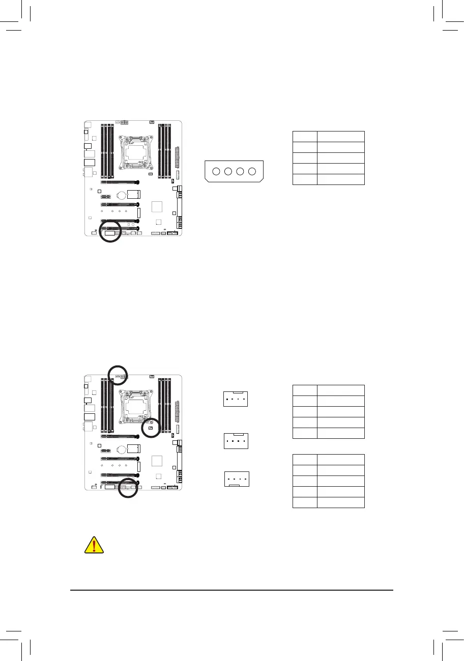
CPU_FAN
1
CPU_FAN:
Pin No. Denition
1 GND
2 +12V
3 Sense
4 Speed Control
SYS_FAN1/2:
Pin No. Denition
1 GND
2 Speed Control
3 Sense
4 VCC
Pin No. Denition
1 VCC
2 GND
3 GND
4 +12V
3) ATX4P (PCIe Power Connector)
The power connector provides auxiliary power to the onboard PCI Express x16 slots. When two or more
graphics cards are installed, we recommend that you connect the power cable from the power supply to
the ATX4P connector to ensure system stability.
1
SYS_FAN1
1
4/5) CPU_FAN/SYS_FAN1/SYS_FAN2 (Fan Headers)
All fan headers on this motherboard are 4-pin. Most fan headers possess a foolproof insertion design.
When connecting a fan cable, be sure to connect it in the correct orientation (the black connector wire is
the ground wire). The speed control function requires the use of a fan with fan speed control design. For
optimum heat dissipation, it is recommended that a system fan be installed inside the chassis.
1
SYS_FAN2
 Loading...