- 26 -
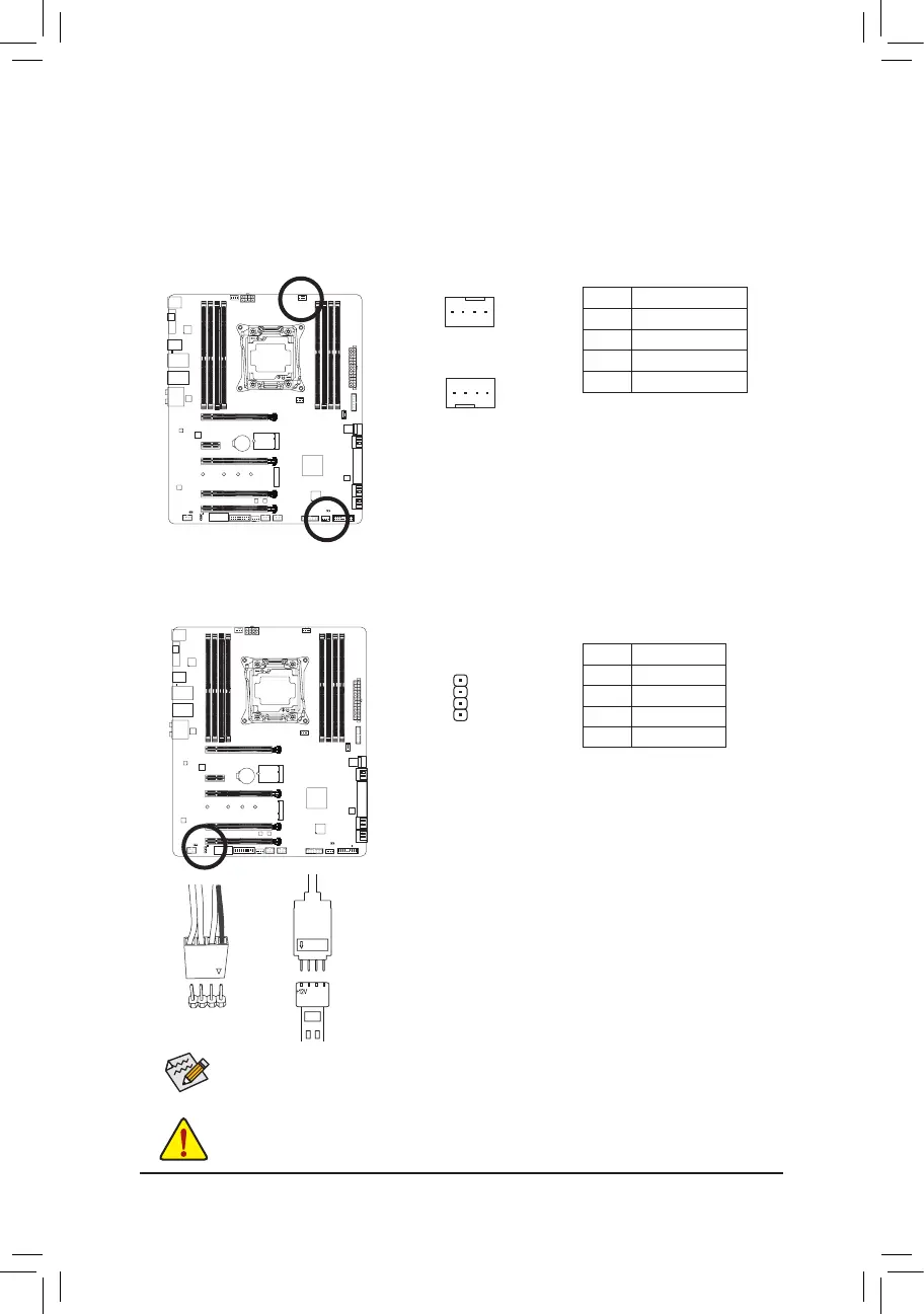
Pin No. Denition
1 GND
2 Speed Control
3 Sense
4 Speed Control
1
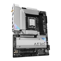
6) CPU_OPT_PUMP/SYS_FAN3_PUMP (Fan/Pump Headers)
The fan/pump headers are 4-pin. Most fan headers possess a foolproof insertion design. When connecting
a fan cable, be sure to connect it in the correct orientation (the black connector wire is the ground wire).
The speed control function requires the use of a fan with fan speed control design. For optimum heat dis-
sipation, it is recommended that a system fan be installed inside the chassis. The headers also provide
speed control for water cooling pumps, refer to Chapter 2, "BIOS Setup," "M.I.T.," for more information.
7) LED_C (RGB LED Strip Extension Cable Header)
Theheadercanbeusedtoconnectastandard5050RGBLEDstrip(12V/G/R/B),withmaximumpower
rating of 2A (12V) and maximum length of 2m.
Pin No. Denition
1 12V
2 G
3 R
4 B
Before installing the devices, be sure to turn off the devices and your computer. Unplug the power
cord from the power outlet to prevent damage to the devices.
1
1
SYS_FAN3_PUMP
CPU_OPT_PUMP
Forhowtoturnon/offthelightsoftheRGBLEDstrip,refertotheinstructionsoninChapter2,
"BIOS Setup."
ConnectoneendoftheincludedRGBLEDstripextensioncabletothe
headerandtheotherendtoyourRGBLEDstrip.Theblackwire(marked
with a triangle on the plug) of the extension cable must be connected to
Pin 1 (12V) of this header. The 12V pin (marked with an arrow) on the
other end of the extension cable must be lined up with the 12V of the LED
strip. Be careful with the connection orientation of the LED strip; incorrect
connection may lead to the damage of the LED strip.
12V
1
Black wire
12V of the
LED strip
 Loading...