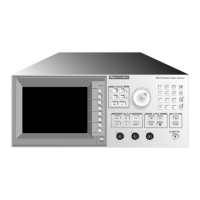
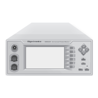
Series 8500A Peak Power Meters
1-6 Manual 20790, Rev. C, November 1998
Auxiliary Inputs/Outputs
Monitor: Provides a voltage proportional to the detected RF envelope.
Rise time is typically 20 ns, output impedance is nominally 50
ohms.
Analog Output Coefficient: 100 mV/dB ±0.5 mV (0 V = 0 dBm)
Offset: ±10 mV
Trigger Input:
TTL
RF Blanking: TTL open collector low during zeroing. Used to control power
source.
V
PROP
F:
(V/GHz) Allows direct entry of frequency from RF power sources
equipped with a VpropF output.
GPIB Interface: Per IEEE STD 488-1978
GPIB Indicators:
REM, TLK, LSN, SRQ, LLO
Remote Operation
Complete setup and measurement capabilities accessible via
GPIB (IEEE 488). Reporting of errors, malfunctions, operational
status, and self-test diagnostics available through serial poll
capability.
Direct Plot Output:
Outputs hardcopy pulse profile plots, with time, date and part
identification, to a GPIB plotter.
GPIB Address: Selectable from front panel
IEEE Interface Functions:
SH1, AH1, T6, L4, SR1, RL1, PP0, DC1, DT1, TE0, LE0
General Specifications
Stored Setups:
Saves settings at power down, and has 10 additional setups in
non-volatile memory.
Power-On Self-Test (POST):
POST is optionally performed at any time. A diagnostic code
indicates the cause and location of any errors.
Reset Control
(rear panel): Returns the instrument to preset (default) condition.
Design and Construction: To the intent of MIL-T-28800C, Type III, Class 5, Style E or F,
Color R
Power Requirements: 100, 120, 220, or 240 Vac ±10%, 50, 60, or 400 Hz ±5%
Power Consumption: Approximately 100 VA
Operating Temperature:
0 to 50 °C (32 to 122 °F)
Non-operating Temperature:
-40 to +65 °C (-40 to +149 °F)


 To Next Page