- 26 -
• Be sure to connect fan cables to the fan headers to prevent your APU and system from overheat-
ing. Overheating may result in damage to the APU or the system may hang.
• Thesefanheadersarenotcongurationjumperblocks.Donotplaceajumpercapontheheaders.
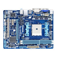
3/4) CPU_FAN/SYS_FAN1/SYS_FAN2/SYS_FAN3/SYS_FAN4 (Fan Headers)
All fan headers on this motherboard are 4-pin. Most fan headers possess a foolproof insertion design.
Whenconnectingafancable,besuretoconnectitinthecorrectorientation(theblackconnectorwireis
thegroundwire).Thespeedcontrolfunctionrequirestheuseofafanwithfanspeedcontroldesign.For
optimum heat dissipation, it is recommended that a system fan be installed inside the chassis.
CPU_FAN/SYS_FAN1:
Pin No. Denition
1 GND
2 +12V /Speed Control
3 Sense
4 Speed Control
SYS_FAN4:
Pin No. Denition
1 GND
2 +12V
3 Sense
4 Reserve
CPU_FAN
SYS_FAN2
SYS_FAN4
SYS_FAN3
1
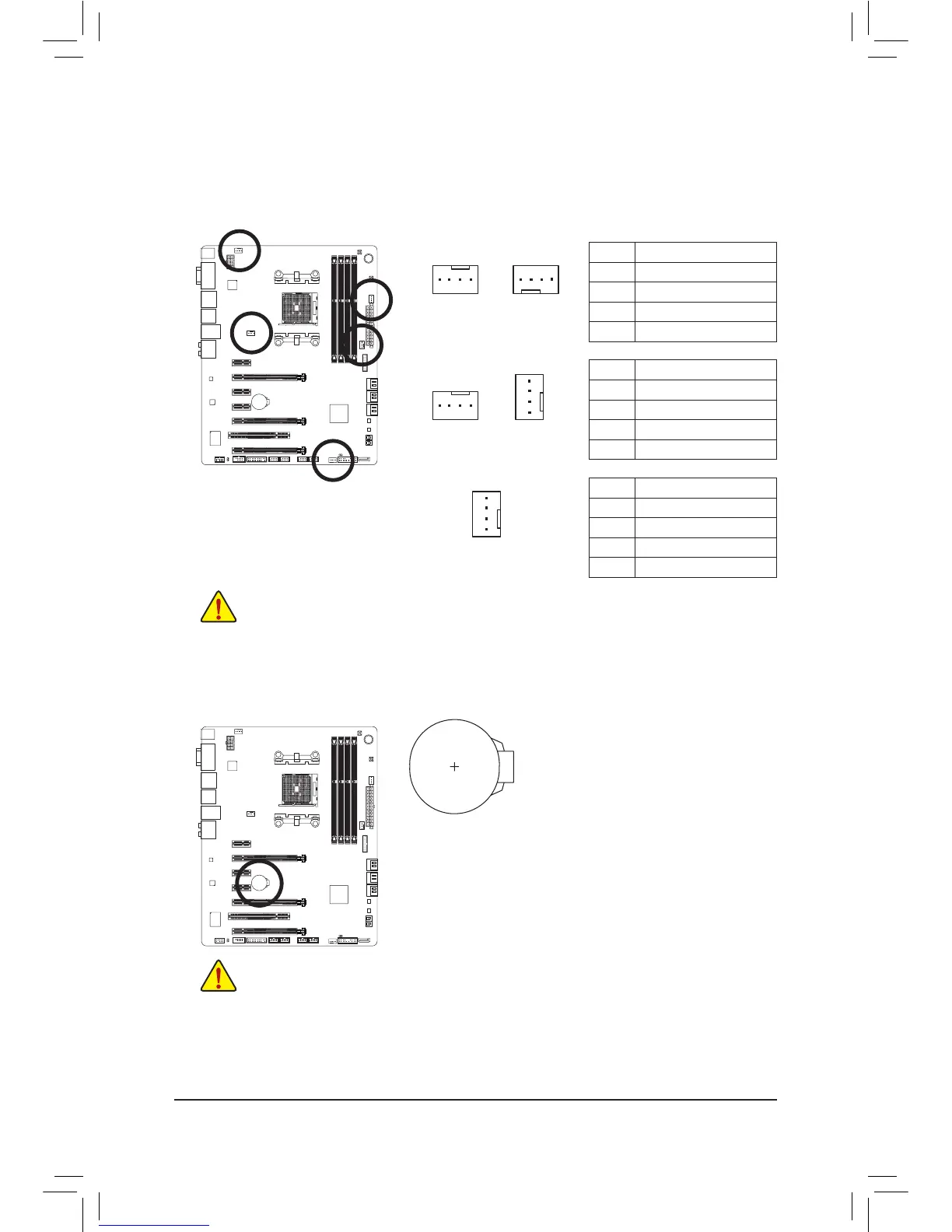
5) BAT (Battery)
Thebatteryprovidespowertokeepthevalues(suchasBIOScongurations,date,andtimeinformation)
in the CMOS when the computer is turned off. Replace the battery when the battery voltage drops to a low
level, or the CMOS values may not be accurate or may be lost.
You may clear the CMOS values by removing the battery:
1. Turn off your computer and unplug the power cord.
2. Gently remove the battery from the battery holder and wait for one minute.
(Oruseametalobjectlikeascrewdrivertotouchthepositiveandnegative
terminalsofthebatteryholder,makingthemshortfor5seconds.)
3. Replace the battery.
4. Plug in the power cord and restart your computer.
• Always turn off your computer and unplug the power cord before replacing the battery.
• Replace the battery with an equivalent one. Danger of explosion if the battery is replaced with
an incorrect model.
• Contact the place of purchase or local dealer if you are not able to replace the battery by yourself
or uncertain about the battery model.
• Wheninstallingthebattery,notetheorientationofthepositiveside(+)andthenegativeside(-)
ofthebattery(thepositivesideshouldfaceup).
• Used batteries must be handled in accordance with local environmental regulations.

 Loading...