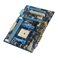
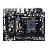
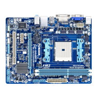
1-1 Installation Precautions
The motherboard contains numerous delicate electronic circuits and components which can become
damagedasaresultofelectrostaticdischarge(ESD).Priortoinstallation,carefullyreadtheuser's
manual and follow these procedures:
• Prior to installation, make sure the chassis is suitable for the motherboard.
• Priorto installation, donot remove orbreak motherboard S/N(Serial Number) stickeror
warranty sticker provided by your dealer. These stickers are required for warranty validation.
• Always remove the AC power by unplugging the power cord from the power outlet before
installing or removing the motherboard or other hardware components.
• Whenconnectinghardwarecomponentstotheinternalconnectorsonthemotherboard,make
sure they are connected tightly and securely.
• Whenhandlingthemotherboard,avoidtouchinganymetalleadsorconnectors.
• Itisbesttowearanelectrostaticdischarge(ESD)wriststrapwhenhandlingelectroniccom-
ponents such as a motherboard, CPU or memory. If you do not have an ESD wrist strap, keep
yourhandsdryandrsttouchametalobjecttoeliminatestaticelectricity.
• Prior to installing the motherboard, please have it on top of an antistatic pad or within an
electrostatic shielding container.
• Before unplugging the power supply cable from the motherboard, make sure the power supply
has been turned off.
• Before turning on the power, make sure the power supply voltage has been set according to
the local voltage standard.
• Before using the product, please verify that all cables and power connectors of your hardware
components are connected.
• To prevent damage to the motherboard, do not allow screws to come in contact with the
motherboard circuit or its components.
• Make sure there are no leftover screws or metal components placed on the motherboard or
within the computer casing.
• Do not place the computer system on an uneven surface.
• Do not place the computer system in a high-temperature environment.
• Turning on the computer power during the installation process can lead to damage to system
components as well as physical harm to the user.
• If you are uncertain about any installation steps or have a problem related to the use of the
product,pleaseconsultacertiedcomputertechnician.
Chapter 1 Hardware Installation

 Loading...
