- 24 -
Hardware Installation
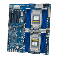
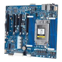
CPU1
CPU0
DIMM_P1_Q1
DIMM_P1_N0
DIMM_P1_M0
DIMM_P1_P0
DIMM_P1_O0
DIMM_P1_R0
DIMM_P1_T0
DIMM_P1_W0
DIMM_P1_X0
DIMM_P1_U0
DIMM_P1_V0
DIMM_P1_S0
DIMM_P0_B0
DIMM_P0_E0
DIMM_P0_F0
DIMM_P0_C0
DIMM_P0_D0
DIMM_P0_A0
DIMM_P0_K0
DIMM_P0_H0
DIMM_P0_G0
DIMM_P0_J0
DIMM_P0_I0
DIMM_P0_L 0
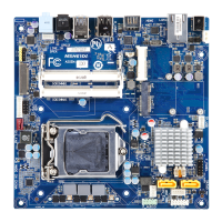
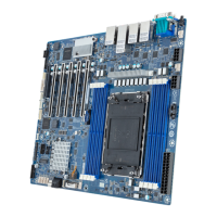
17) BP_1 (HDD Backplane Board Header)
Pin No. Denition Pin No. Denition
1 Reserved 2 BPMI DIN/OUT
3 GND 4 BPMI DIN/IN
5 BPMI_LOAD 6 GND
7 BPMI_CLK 8 PLD_Program_EN
9 GLED_AMB_N 10 GLED_GRN_N
11 FAN_IRQ_N 12 Reserved
13 BP_SCL 14 GND
15 BP_SDA 16 BP_RST_N
17 SMB_U2_TMP_SCL 18 GND
19 SMB_U2_TMP_SDA 20 I2C_DEV_RST
21 PH_HP_SCL0 22 GND
23 PH_HP_SDA0 24 GND
25 PH_HP_SCL1 26 GND
27 PH_HP_SDA1 28 GND
15 P3V3_AUX 30 P3V3_AUX
29
30
2 1
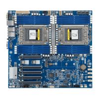
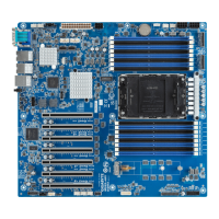
CPU1
CPU0
DIMM_P1_Q1
DIMM_P1_N0
DIMM_P1_M0
DIMM_P1_P0
DIMM_P1_O0
DIMM_P1_R0
DIMM_P1_T0
DIMM_P1_W0
DIMM_P1_X0
DIMM_P1_U0
DIMM_P1_V0
DIMM_P1_S0
DIMM_P0_B0
DIMM_P0_E0
DIMM_P0_F0
DIMM_P0_C0
DIMM_P0_D0
DIMM_P0_A0
DIMM_P0_K0
DIMM_P0_H0
DIMM_P0_G0
DIMM_P0_J0
DIMM_P0_I0
DIMM_P0_L 0
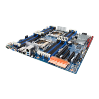
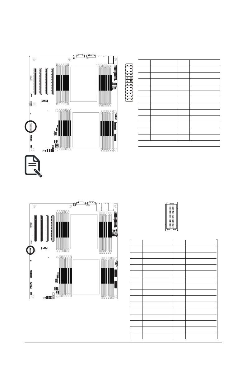
16) FP_1 (Front Panel Header)
Connect the power switch, reset switch, speaker, chassis intrusion switch/sensor and system status indicator
on the chassis to this header according to the pin assignments below. Note the positive and negative pins
before connecting the cables.
The front panel design may differ by chassis. A front panel module mainly consists of power switch,
reset switch, power LED, hard drive activity LED, speaker etc. When connecting your chassis front
panel module to this header, make sure the wire assignments and the pin assignments are matched
correctly.
Pin No. Denition Pin No. Denition
1 Power LED+ 2 5V Standby
3 No Pin 4 ID LED+
5 Power LED- 6 ID LED-
7* HDD LED+ 8 System Status LED+
9* HDD LED- 10 System Status LED-
11 Power Button 12 LAN1 Active LED+
13 GND 14 LAN1 Link LED-
15 Reset Button 16 SMBus Data
17 GND 18 SMBus Clock
19 ID Button 20 Case Open
21 GND 22 LAN2 Actve LED+
23 NMI Switch 24 LAN2 Link LED-
*Note: Pin 7 & Pin 9 are reserved for Gigabyte systems.
2423
 Loading...