- 29 -
Hardware Installation
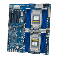
CPU1
CPU0
DIMM_P1_Q1
DIMM_P1_N0
DIMM_P1_M0
DIMM_P1_P0
DIMM_P1_O0
DIMM_P1_R0
DIMM_P1_T0
DIMM_P1_W0
DIMM_P1_X0
DIMM_P1_U0
DIMM_P1_V0
DIMM_P1_S0
DIMM_P0_B0
DIMM_P0_E0
DIMM_P0_F0
DIMM_P0_C0
DIMM_P0_D0
DIMM_P0_A0
DIMM_P0_K0
DIMM_P0_H0
DIMM_P0_G0
DIMM_P0_J0
DIMM_P0_I0
DIMM_P0_L 0
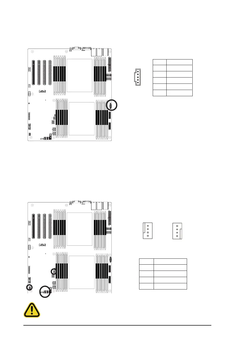
5/9/10/11/12/13) CPU0_FAN/CPU1_FAN/SYS_FAN4/SYS_FAN3/SYS_FAN2/SYS_FAN1 (FAN
Headers)
Themotherboardhasone4-pinCPUfanheader(CPU_FAN),andve4-pin(SYS_FAN)systemfanheaders.
Most fan headers possess a foolproof insertion design. When connecting a fan cable, be sure to connect
it in the correct orientation (the black connector wire is the ground wire). The motherboard supports CPU
fan speed control, which requires the use of a CPU fan with fan speed control design. For optimum heat
dissipation, it is recommended that a system fan be installed inside the chassis.
1
1
PinNo. Denition
1 GND
2 +12V
3 Sense
4 Speed Control
•
Be sure to connect fan cables to the fan headers to prevent your CPU and system from
overheating. Overheating may result in damage to the CPU or the system may hang.
•
Thesefanheadersare notconfiguration jumperblocks. Donot placea jumpercaponthe
headers.
4
4
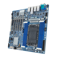
4) PMBus Connector
The Power Management Bus (PMBus) is a variant of the System Management Bus (SMBus) which is
targeted at digital management of power supplies.
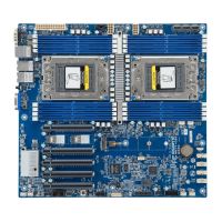
CPU1
CPU0
DIMM_P1_Q1
DIMM_P1_N0
DIMM_P1_M0
DIMM_P1_P0
DIMM_P1_O0
DIMM_P1_R0
DIMM_P1_T0
DIMM_P1_W0
DIMM_P1_X0
DIMM_P1_U0
DIMM_P1_V0
DIMM_P1_S0
DIMM_P0_B0
DIMM_P0_E0
DIMM_P0_F0
DIMM_P0_C0
DIMM_P0_D0
DIMM_P0_A0
DIMM_P0_K0
DIMM_P0_H0
DIMM_P0_G0
DIMM_P0_J0
DIMM_P0_I0
DIMM_P0_L 0
5
PinNo. Denition
1 PMBus Clock
2 PMBus Data
3 PMBus Alert
4 GND
5 3.3V Sense
 Loading...