Turn signals system check
The circuit of the turn indicators is controlled by the electrical control device and the instrument panel.
In the event of a malfunction, proceed as follows:
1. Check the function of the bulbs
2. Check the function of the turn signal indicator switch
3. Without disconnecting the instrument panel, with the key switch in position ON and with the engine
stop switch in position RUN, check for intermittent voltage between terminals 9-ground and 10-ground
of the large 20-pin connector.
If there is no voltage, check the wiring and the correct function of the electrical control units. If the fault
persists, replace the instrument panel.
Lights list
LIST OF BULBS
Specification
Desc./Quantity
1 High-beam / low-beam headlights 2 12V-55W, halogen (H7)
2 Position light / front headlight 2 12V-5W, all-glass
3 Turn indicator bulb 4 12V-10W, spherical
4 Tail light bulb and light 1 12V-21/5W, spherical, twin-filament
5 Licence plate bulb 1 12V-5W, all-glass
6 Helmet compartment bulb 1 12V-5W, cylindrical
Fuses
The electrical system is equipped with:
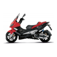
1. Six fuses "A" located on the shield back plate
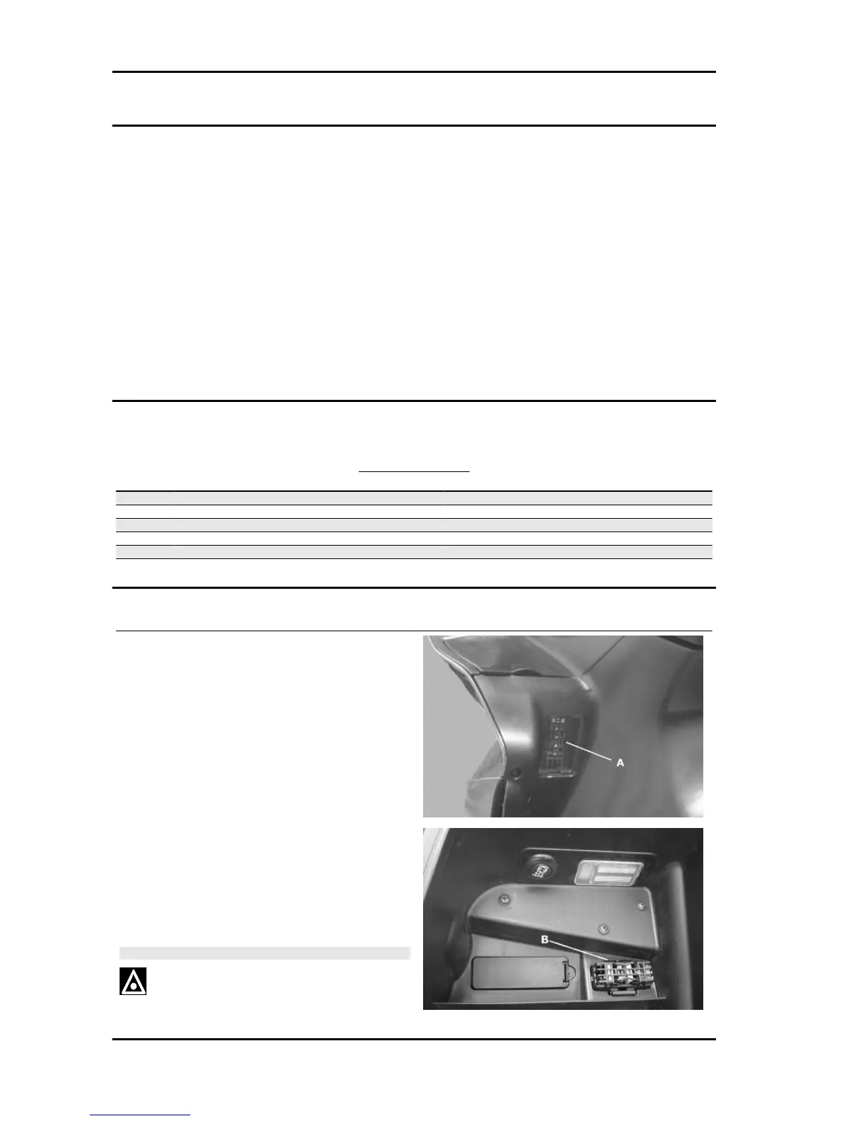
2. Five fuses "B" located in the helmet compart-
ment
3. One fuse of 30A "D" (main fuse), located near
the battery on the left-hand side, under which is
also a replacement fuse.
The rating of the various fuses are stamped on the
fuse holders "C".
To replace the fuse, use the gripper provided in the
tool bag.
The table shows the position and characteristics
of the fuses installed in the scooter.
CAUTION
BEFORE REPLACING A BLOWN FUSE, FIND AND SOLVE
THE FAILURE THAT CAUSED IT TO BLOW. NEVER TRY
Electrical system Nexus 500 euro 3
ELE SYS - 62