FAULT 4
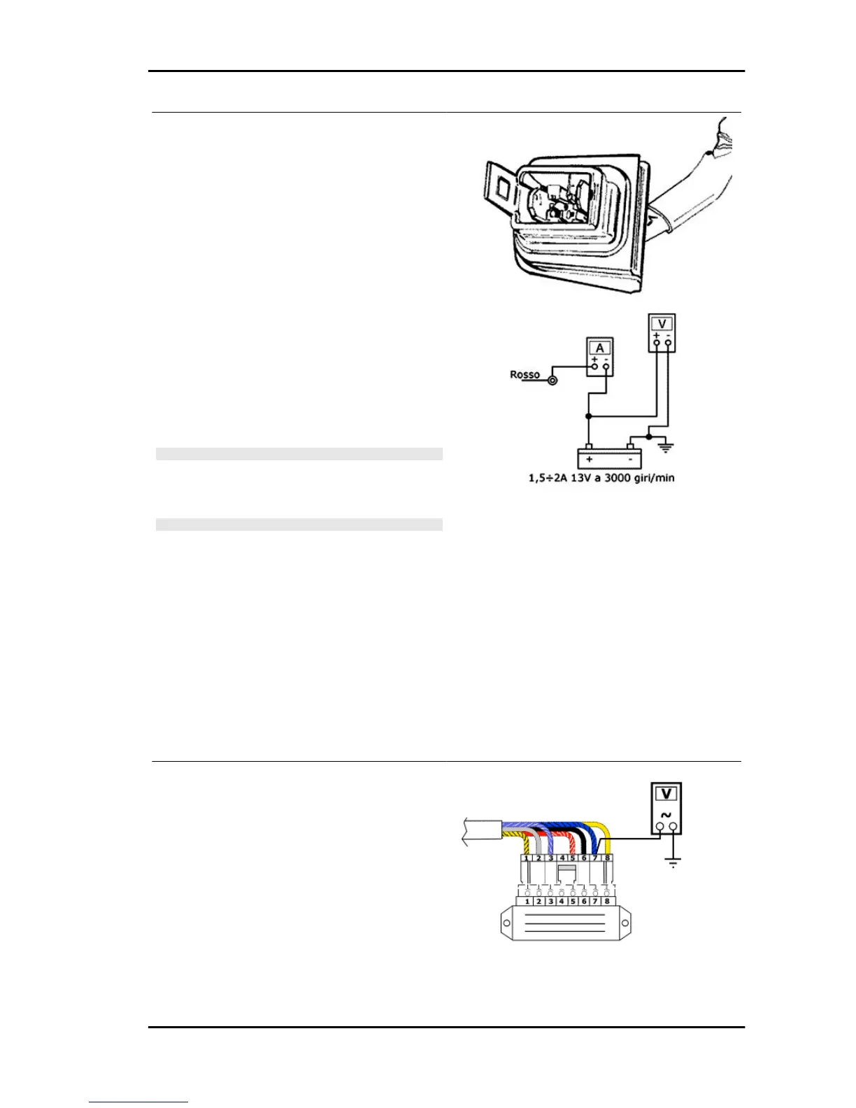
Start the vehicle and make sure that when the
tester is placed between the connection of the red
wire and yellow one on the stator, the voltage de-
livered by the generator is within the indicated
value. In the event of a fault check the continuity
of the stator or continue with the checks.
Insert an ammeter between the stator (red wire)
and the battery and use a tester to make sure that
the current delivered at 3000 rpm and the battery
maintained between 12 and 13 V is as indicated.
If the measured values are lower than those pre-
scribed, replace the regulator otherwise replace
the battery.
N.B.
BEFORE CARRYING OUT THE CHECKS ON THE REGU-
LATOR AND RELATIVE SYSTEM, IT IS ALWAYS GOOD
PRACTICE TO CHECK THAT THERE IS CONTINUITY BE-
TWEEN THE BLACK CABLE AND THE GROUND.
N.B.
TO KEEP THE BATTERY BETWEEN 12 AND 13V, CAUSING
CURRENT ABSORPTION BY THE SYSTEM, A 12V - 35W
BULB CONNECTED BETWEEN THE + BATTERY AND
GROUND CAN BE USED.
Specific tooling
020331Y Digital multimeter
Characteristic
Distributed current
1.5 to 2A
Voltage distributed at 3000 rpms
25 to 30V
FAULT 5
If the turn indicators do not work, do the following:
•
Without removing the connector from
the voltage regulator, move the key-
controlled switch to ON and verify the
presence of intermittent voltage be-
tween contact 7 and the ground. If
there is voltage, the failure must be at-
tributed to the flashing indicator switch
DNA 50 Electrical system
ELE SYS - 53


 To Next Page