12
Issue: 8 (Applies to firmware 2387 6.09 onwards)
Document number: 1390-PS-0039
Cabling and junction box
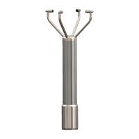
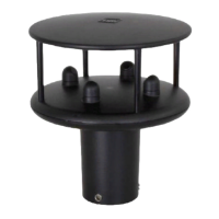
If the WindObserver 65 unit is fitted with a flying 9 pair cable attached this must be terminated in a suitable terminal box
to IP66 or better, fitted with glands to prevent moisture ingress.
The cable type from the terminal box to the host system must be as specified above. If any cable is to be exposed to
mechanical damage, it must be enclosed in a suitable conduit or cable tray. The cable must be securely fixed with cable
clamps or equivalent at regular intervals such that the WindObserver cable gland does not support the cable weight.
The gland area at the base of the WindObserver 65 should not be directly exposed to moisture, as whilst the gland is
sealed when mated, the anemometer is vented to air at the base to avoid pressure build up. If an IP66 rating is essential
or the unit is mounted other than ‘right way up’ use the gasket provided in the mounting kit and apply additional
sealing compounds around the base.
4.6. Power supplies
All WindObserver 65 units
Sensor Supply: -
Voltage 9 to 30v DC
Current 30mA Average. 50mA Max @12v dc
• The WindObserver 65 has reverse polarity protection.
Wind Observer Units with Heating
Heater Supply: -
Voltage 22V to 30V (max) AC RMS or DC.
Current allow for 3A.
The AC Supply must be isolated from Mains Supply.
• The heating module requires a separate power supply.
• Heater Cable length should be minimised to avoid cable volt drops and ensure maximum voltage received at
the Anemometer.
• The heating (H command) is enabled as a default condition. If heating is not required enabled, then the H
command must be set for H1.
• Each transducer is heated independently and will be enabled when ambient temperature drops below the
activation temperature and disabled when the target temperature is reached.
The WindObserver 65 has reverse polarity protection.