47
Issue: 8 (Applies to firmware 2387 6.09 onwards)
Document number: 1390-PS-0039
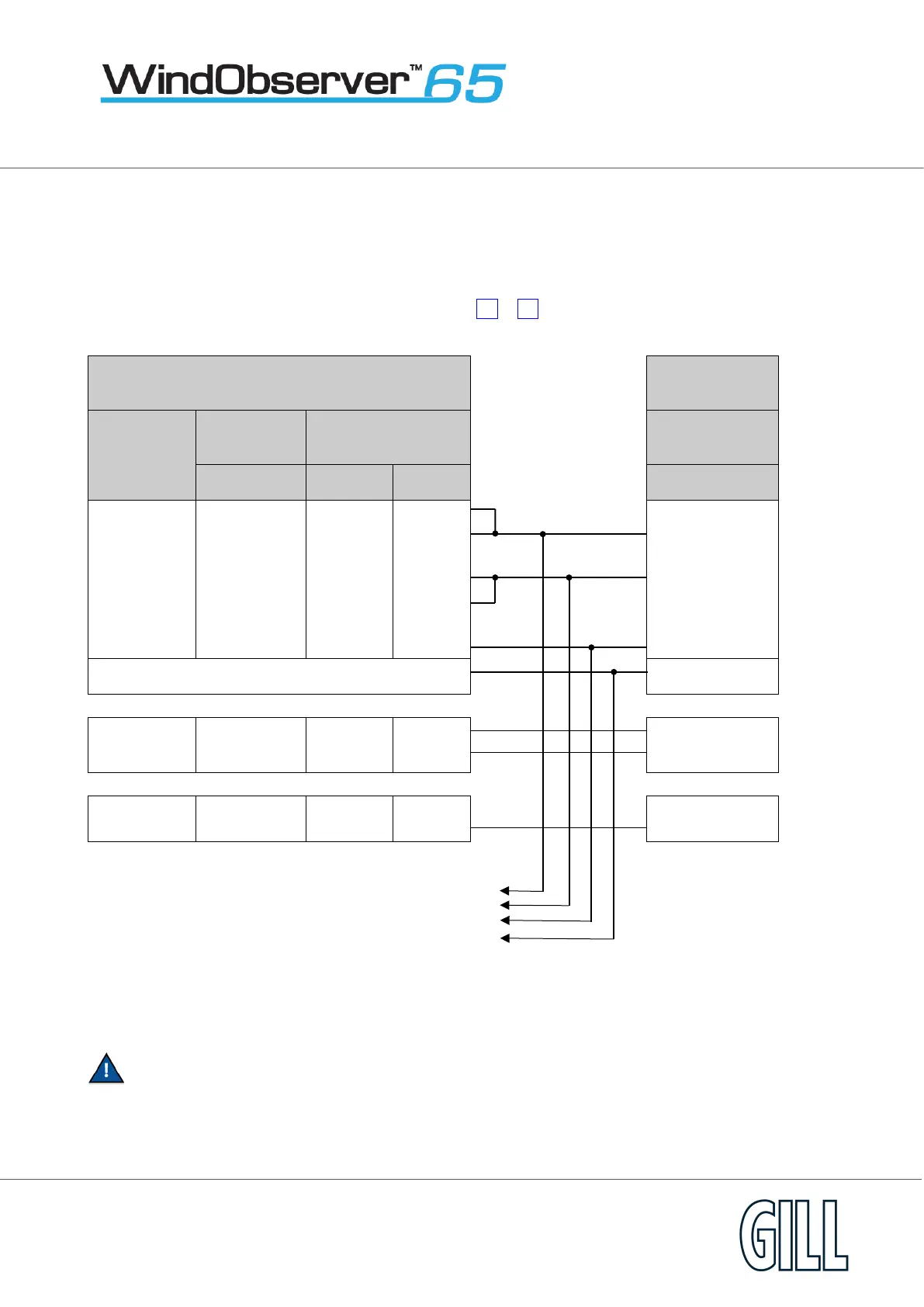
Appendix D - Networking
Before coupling units into a network:
• Each device must be configured with a unique Unit Identifier (letter A to Z) however in multi drop systems
it could be advised to avoid using letters A-F, KMN and P as they could appear in the data string.
• Unit must be set for half duplex mode (E2 setting) see Half Duplex Operation (page 48 ).
• I
t must be configured to a tri-state polled mode M3 or M4.
See also Appendix F - Configuring
Logger
Signal
Names
Connector
*
For Power Supply Information see Appendix A.
Each unit in the network will require its own power supplies.