43
Issue: 8 (Applies to firmware 2387 6.09 onwards)
Document number: 1390-PS-0039
Appendix C - Connections and default setup
Connections
Important any cable wires not used should be isolated and grounded at the terminating equipment/user end.
Do NOT connect the unit’s 0V, heating –ve, or digital 0V to the screen or earth.
On units with integral cable the screens of each pair are joined together inside the anemometer - these should be
joined to the cable screen(s) of any further cable run. Avoid long grounding loops. Digital OV should be used in
conjunction with RS422 TX RX lines in order to improve noise immunity.
Earthing or grounding
To ensure correct operation, and for maximum protection against lightning, the anemometer MUST be correctly earthed
(grounded) via its mountings. Inadequate Earthing will degrade anemometer performance, particularly in the presence
of radio frequency interference.
See page 17, Fig 1
Suggested mounting bracket and Earthing (grounding) arrangements
The unit MUST be connected to an appropriate grounding point with a minimum of 6mm² copper wire, via the M5 base
screws. The cable screens must be joined with any cable screen continuing from the unit’s cable via a junction box. The
primary earth for the anemometer must be provided via the base screws and not via the cable screens.
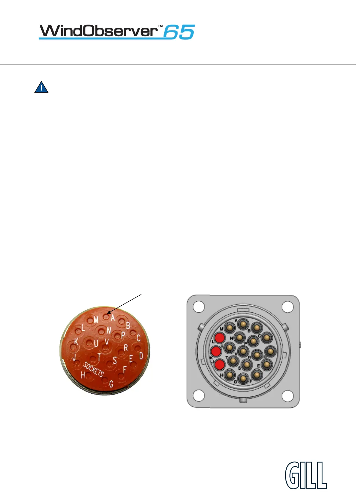
View of the WindObserver 65 base connector variant
Supplied Plug Anemometer Socket