0020140413_01 - 09/12 - Glow-worm
7 Appliance installation
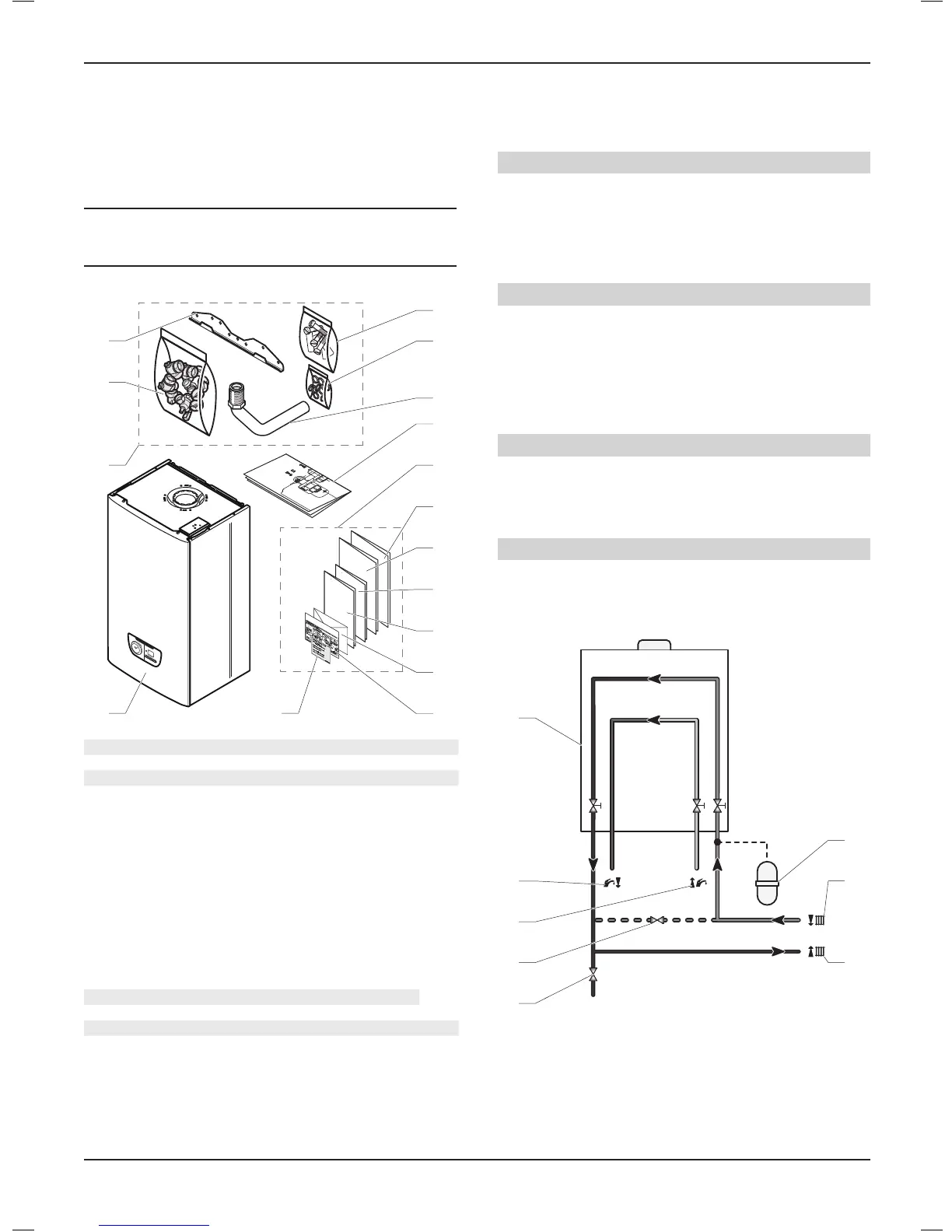
7.1 Scope of delivery
The appliance is delivered in a single carton with a document
pack and ttings.
i
IMPORTANT:
The ues package will be ordered according to the
conguration of the installation.
• Please check the contents.
2
2.1
2.2
2.3
2.5
2.4
3
4
4.1
4.2
4.3
4.4
4.5
Key
1 Boiler (x1)
2 Accessories bag (x1)
2.1 Connection bag (x1)
- Heating return valve (x1)
-Coldwaterinletvalve (x1)
-Heatingowvalve (x1)
-Domestichotwaterconnection (x1)
- Gas isolation valve (x1)
2.2 Hanging bracket (x1)
2.3 Screwsandwallplugsbag (x1)
2.4 Seals bag (x1)
- Flat seal ½" (x2)
- Flat seal ¾" (x5)
-Flatsealforcoldwaterinlet¾" (x4)
2.5 PRV pipe (x1)
3 Wall template (x1)
4 Documents bag (x1)
4.1 Installation and servicing manual (x1)
4.2 Flue book (x1)
4.3 Instructions for use (x1)
4.4 Extendedguaranteeleaet (x1)
4.5 Guarantee envelope pack (x1)
4.6 Magnetic lighting instruction label (x1)
4.7 Gas conversion label (x1)
7.2 Recommendations before installing
7.2.1 Domestichotwatercircuitdesign
Water pressure
The minimum working pressure to obtain the maximum domestic
ow is 1,0 bar.
The maximum working pressure of the domestic hot water circuit
is 10 bar. If the cold water supply pressure exceeds this, then a
pressure-reducing valve must be tted in the supply to the boiler.
‘Hard’ water areas
The temperatures within the heat exchanger are limited by the
boiler control system to minimise scale formation within the hot
water pipework. However, in areas where the water is ‘hard’ (i.e.
more than 200 mg/L of calcium carbonate), it is recommended
that the hot water setting is reduced and that a scale reducer is
tted, refer to the manufacturer’s instructions or consult the local
water company for additional advice.
Domestic water ow rate
The domestic hot water ow has a restrictor, factory tted, which
reduces the ow to a maximum of:
- 24 : 8/min,
- 28 : 10/min,
Central Heating water ow rate
If it is necessary to alter the ow rate, the system can be tted
with a lockable balancing valve in the main ow or return pipes.
- Heating circuit design
5
4
3
2
6
7
8
Key
1 Drain point
2 External bypass (if required)
3 Domestichotwaterout
4 Domesticcoldwatersupplyin
5 Boiler
6 Additional expansion vessel (if required)
7 Heating return circuit
8 Heatingowcircuit
9 Optional balancing valve
INSTALLATION
- 9 -
 Loading...