0020140413_01 - 09/12 - Glow-worm
11.6.2 Gas Rate
• Make sure that all other gas burning appliances and pilot
lights are o.
• Check the gas rate using the gas meter test dial and stop
watch, at least 10 minutes after the burner has lit, see table
below for approximate rates.
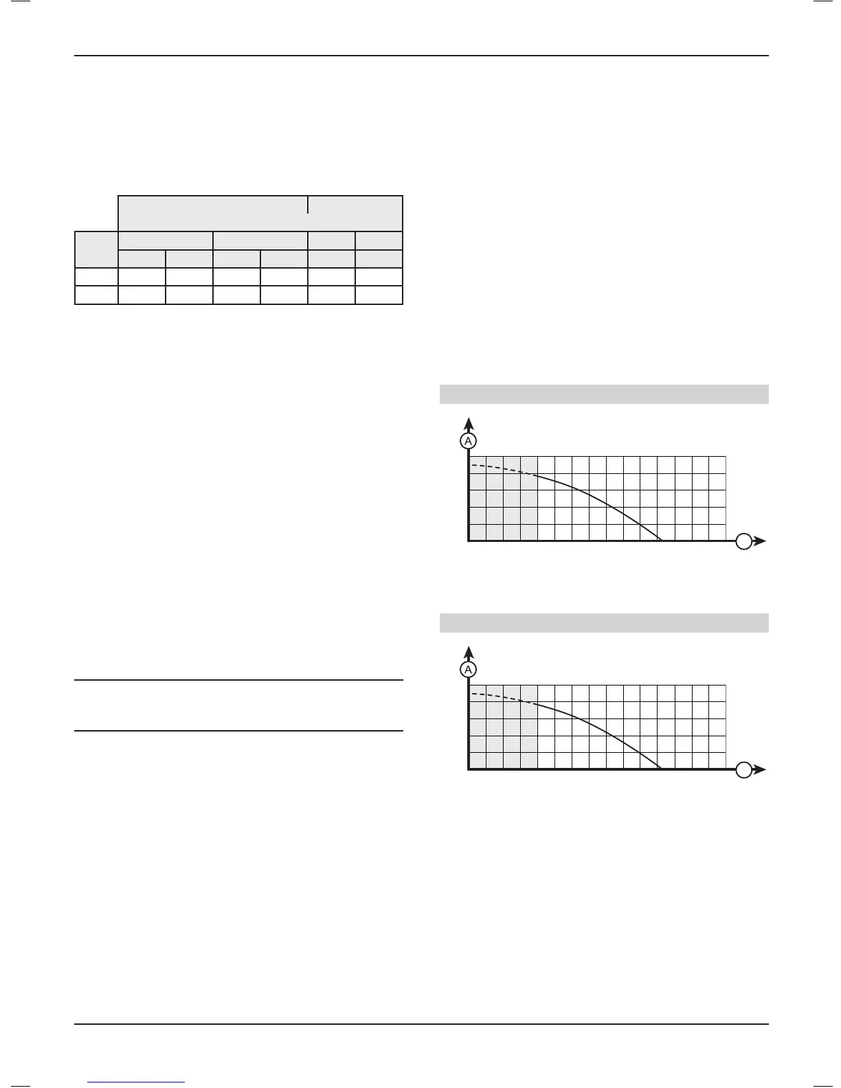
Gas rates (G20) Gas rates (G31)
(approx) after 10 mins from cold
Model
MIN MAX MIN MAX
m
3
/h ft
3
/h m
3
/h ft
3
/h kg/h kg/h
24 0.85 30 2.54 89.7 0.62 1.87
28 0.88 31.1 2.96 104.05 0.645 1.87
In communal or LPG installations where the gas rate cannot be
measured it is acceptable to measure the combustion rate as
described in the servicing section.
• On completion, press the "reset" button to reset the boiler.
• Gas rates for both central heating and hot water can be veried
using the test program P.03 and P.01 respectively.
11.7 Testing heating system
• Ensure that the external controls and programmer are calling
for heat.
• Fully open all radiator valves, see chapter "Appliance
installation > Recommendations before installing > Heating
circuit design".
• Activate the C.H. function on the appliance's control panel.
• Balance the radiators as required to give the required system
dierential.
• Turn o all radiators that can be shut o by the user and check
to see if less than the maximum dierential allowed of 20°C
can be achieved across ow and return.
i
IMPORTANT:
Should the appliance require adjustment refer to the
"Specic adjustment" section overleaf.
• Allow the system to reach maximum temperature then switch
o the boiler by isolating from the electrical supply.
• Drain the entire system rapidly whilst hot, using the drain taps
at all the low points of the system. Fill and vent the system as
described previously in chapter "Commissioning > Filling the
CH system (Central heating)".
• Adjust the boiler temperature controls and any system controls
to their required settings.
11.8 Testingdomestichotwatersystem
• Open a hot-water tap.
• Check that the temperature obtained is compliant with the
setting on the appliance.
11.9 Completion
• Ensure that the magnetic lighting instruction label is placed on
the surface of the boiler casing.
GB: It is a requirement that the “Benchmark” Installation,
Commissioning and Service Record is completed and left with the
user.
IE: it is necessary to complete a “Declaration of Conformity” to
indicate compliance to I.S.813. An example of this is given in the
current edition of I.S.813.
12 SpeciedAdjustment
12.1 Heating circuit adjustment
By pass operation is automatic and not adjustable.
• If necessary, t an external by-pass.
Easicom 24
B
0
10
20
30
40
50
500
1000
1500
Key
A Availablepressurebetweenheatingowandreturn(kPa)
B Heatingcircuitowrate(l/h)
Easicom 28
B
0
10
20
30
40
50
500
1000
1500
Key
A Availablepressurebetweenheatingowandreturn(kPa)
B Heatingcircuitowrate(l/h)
INSTALLATION
- 23 -
 Loading...