0020140413_01 - 09/12 - Glow-worm
7.4 Mounting
• Make sure that the equipment used for implementing the
installation is compatible with that of the appliance.
• Determine the assembly location. See the "Appliance location"
chapter.
117
892
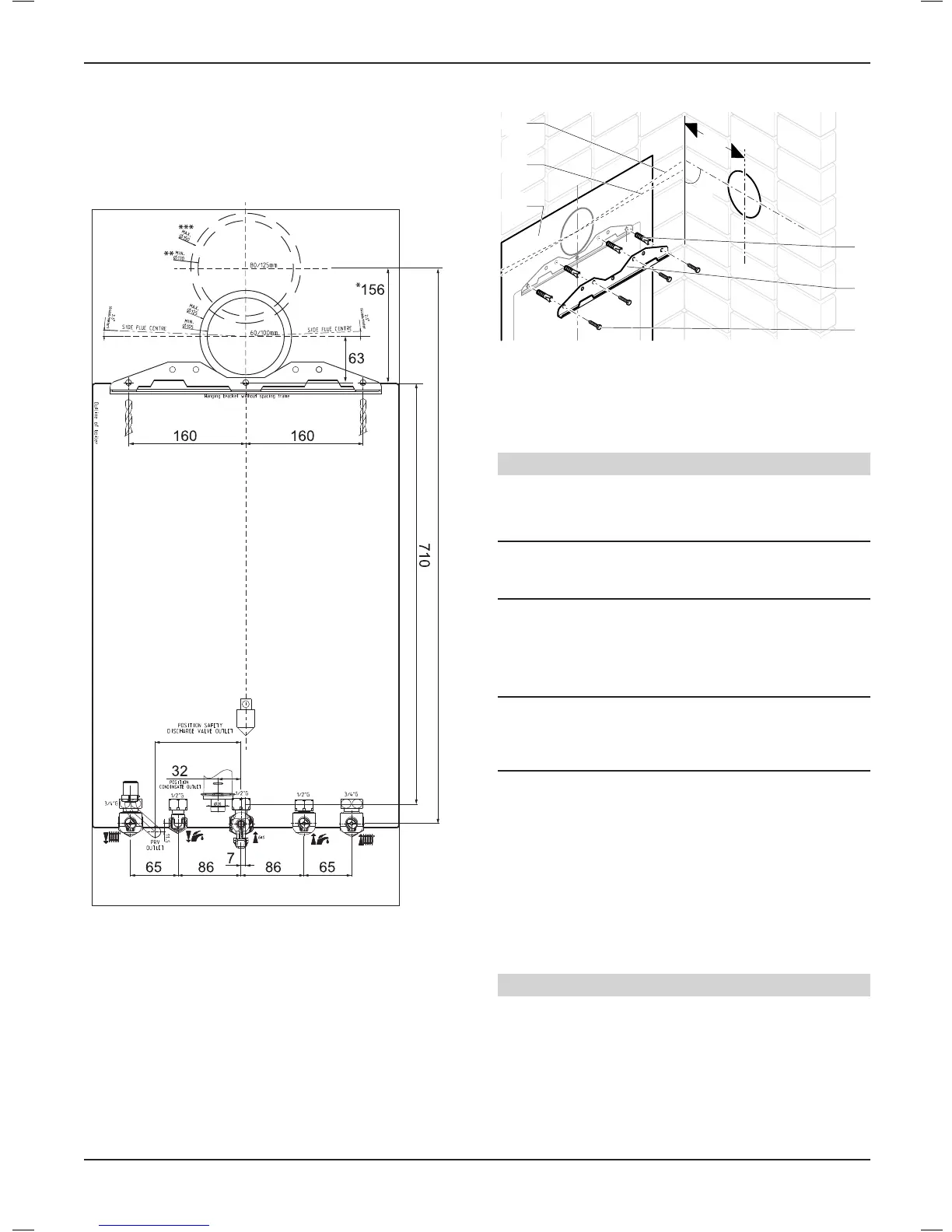
* 80/125ue=Ø150mm
** 80/125ue=Ø130mm
*** 80/125ue=156mm
• Take the wall template and place in the desired position
on the wall, giving due consideration to the required boiler
clearances, see chapter "Appliance location > Clearances", and
the ue you are tting.
7.4.1 Fixingtothewall
130
90°
4
5
6
2
1
3
Key
1 Wall template
2 Standarduelengthhorizontal
3 2.5°44mm/metreinclinedextendeduelength
4 Wall plug
5 Hanging bracket
6 Screw
Flue hole cutting
• Mark the position of the ue centre.
• Remove the wall template, then drilling the ue hole.
i
IMPORTANT:
The ue is designed with an internal fall of 44mm/metre
(2.5
o
), therefore the hole can be drilled horizontally.
• Use a 105mm diameter core drill for external access ue
installation (60/100 ue) (80/125 ue > Ø130mm).
• Use a 125mm diameter core drill for internal access only ue
installation (60/100 ue) (80/125 ue > Ø150mm).
i
IMPORTANT:
If ue extension pipes are to be used then a core drill
size of 125mm is required. This will allow the extension
pieces to slope at 44mm/metre (2.5
o
) towards the boiler.
• If tting a side ue, extend the ue centre line into the corner
then 130mm along the adjacent wall.
• If tting an extended side ue, determine the ue hole centre
by extending the dashed inclined line on the template to the
side wall. This dashed line is drawn at 44mm/metre (2.5o)
rise from the boiler. Where this line reaches the side wall, a
horizontal line should be marked. The vertical centre line of
the ue should then be marked at 130mm from the back wall.
To allow for the ue passing through the wall at this angle
a 125mm hole should be drilled irrespective of internal or
external installation.
Hanging bracket xing
Due to the varied site conditions the xings supplied may not be
suitable, please make sure that those used are.
• Drill the holes for the xing screws in accordance with the wall
template.
• Fix the hanging bracket on the wall.
INSTALLATION
- 11 -
 Loading...