0020140413_01 - 09/12 - Glow-worm
17.2.2 Control box
24
V
230
V
1
Key
1 Control box
• Position the control box (1) into the service position.
17.3 Combustion check and setting the air/gas
ratio valve
17.3.1 Competency to carry out the check of
combustion performance
i
IMPORTANT:
BS 6798: 2009 Specication for installation and
maintenance of gas-red boilers of rated input not
exceeding 70kW net advises that:
- The person carrying out a combustion measurement must be
assessed as competent in the use of a ue gas analyser and
the interpretation of the results.
- The ue gas analyser used should be one meeting the
requirements of BS7927 or BS-EN50379-3 and be calibrated in
accordance with the analyser manufacturers’ requirements.
- Competence can be demonstrated by satisfactory completion
of the CPA1 ACS assessment, which covers the use of
electronic portable combustion gas analysers in accordance
with BS 7967, parts 1 to 4.
• Ensure that the gas analyser is set to the correct fuel setting.
• Select the “
+ ”, constant central heating with DHW
function by pressing the “
” button repeatedly, refer to
commissioning section. The boiler should re automatically.
i
IMPORTANT:
Safe combustion can only be veried by measuring CO/
CO
2
ratio. This must not exceed the value shown in the
table opposite.
17.3.2 Preliminaries
Prior to, during servicing and after any maintenance or changed
parts, the following inspection must be carried out.
• The integrity of the ue system and ue seals.
• The integrity of the appliance combustion circuit and relevant
seals.
• A visual inspection of the ame quality.
• Electrical, gas and water connections.
• System pressure.
• The combustion performance, refer to the following procedure.
• The operational gas inlet pressure and gas rates, refer to the
commissioning section paragraph 12.5. Correct any fault
before continuing.
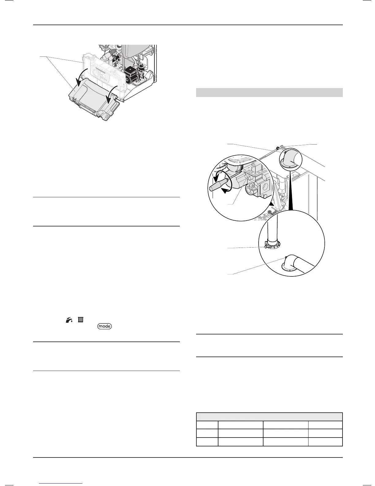
Combustion check and setting the air/gas ratio
• Remove the front casing panel and hinge down the control box.
Taking care not to touch any internal components, proceed as
follows:
• Connect the CO
2
combustion analyser to the relevant test
point.
1
2
3
2B
2A
Key
1 Throttle
2 Combustion analyser sample point
2A Flueelbow
2B Verticalueadaptor
3 Cap
17.3.3 Maximum rate check and adjustment
i
IMPORTANT:
To verify the maximum gas rate CO2 setting the
appliance must be checked at the maximum rate.
• Activate the test mode "P.01" and set the value to HI in order to
force the burner at P. max. See chapter "Specic adjustment >
Appliance technical settings and parameter list > Test modes".
• Wait approximately 5 minutes to read a stabilised CO
2
value.
• Check that the value is within the range specied in table in
the “check” column.
G20 Burner % CO
2
Model Check (case on) Setting(caseo) CO/CO
2
ratio
24
9.2 ± 0.3% 9 ± 0.2% 0.004
28
9.2 ± 0.3% 9 ± 0.2% 0.004
MAINTENANCE
- 34 -
 Loading...