1. Ensure the connection of the DLC (VCI) loopback adapter (Part Number 3000109) to the VCI module of the Tech 2.
2. Navigate to the self test option: At the Tech 2 Main Menu, select F3: Tool Options, and then choose Self Test.
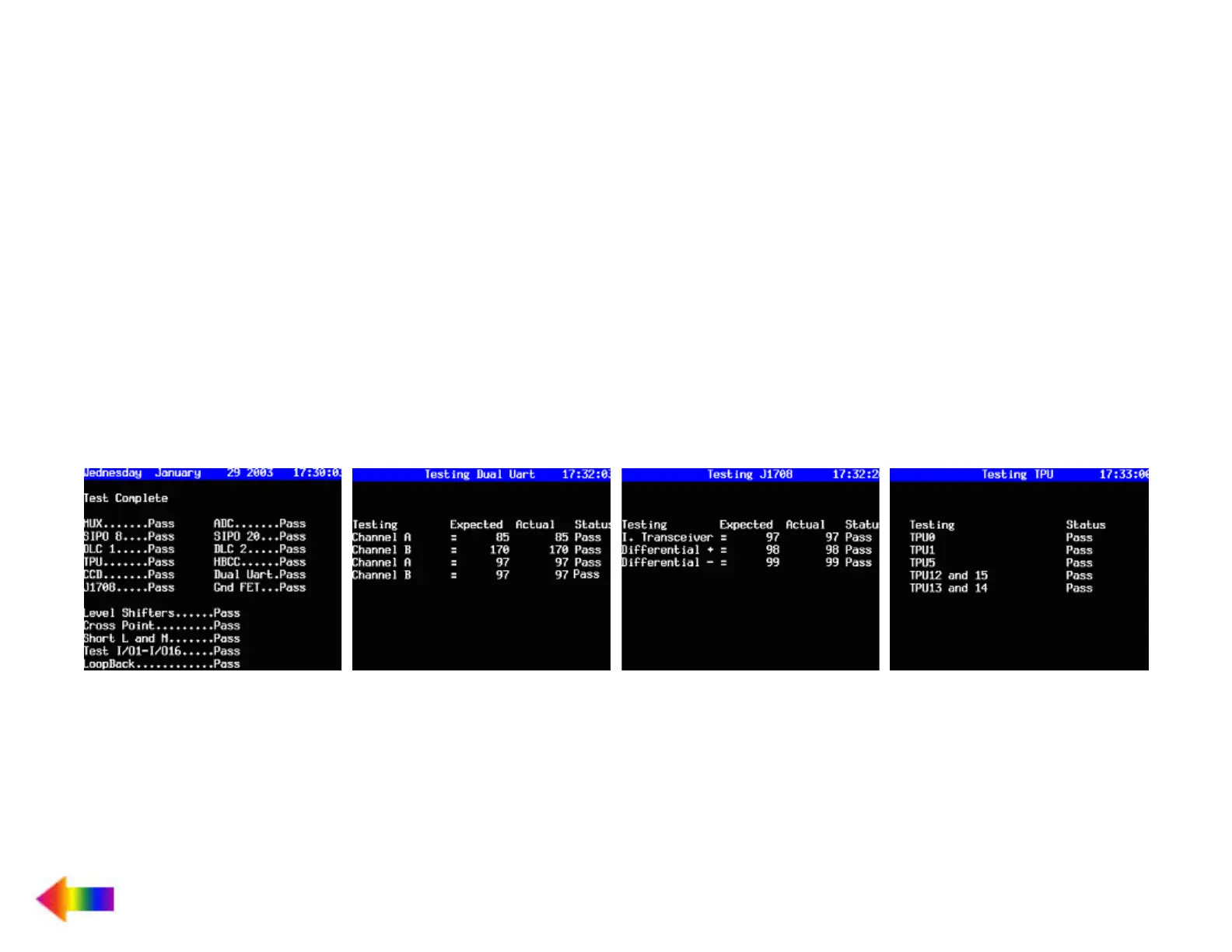
3. Select the test F2: Automated VCI. Screen 1 (shown below) should appear if the test passes. (Note: If failures are noticed on the
CCD test and the HBCC test, these will not affect diagnostics on GM vehicles.)
4. Select F4: Selectable VCI and press the More Test soft key. Choose F1: VCI Dual Uart. Screen 2 appears if the test passes.
5. Select F5: VCI J1708, and Screen 3 will display.
6. Select F6: VCI TPU, and Screen 4 will display.
NOTE: When performing the TPU test, it is critical that TPU12 and TPU15 indicate “Pass.” If these two TPU channels indicate “Fail,”
or if they are not present in the above list, then the VCI module for the Tech 2 is possibly damaged.
7. Insert the DLC Burndy cable into the Tech 2/VCI and the DLC loopback adapter at the end of the cable and repeat the tests listed
above. (Note: When running the VCI TPU test, TPU12 and TPU15 must show up as pass. If they indicate, “fail,” or if they are not
present on the screen, then the cable might be damaged. This is assuming that TPU12 and TPU15 passed with the VCI loopback
adapter connected directly into the VCI. Also, when performing the VCI TPU test, TPU13 and TPU14 will not appear on the screen
when running this test with the DLC Burndy cable inserted into the Tech 2/VCI and the loopback adapter at the end of the cable.)
Screen 1
Screen 2 Screen 3 Screen 4
GM Tech 2 / VCI / Cable Test