Riduttori
22
GSM_mod.MT01 IGBD 0.0
RX
Series
Industrial
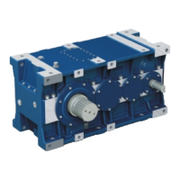
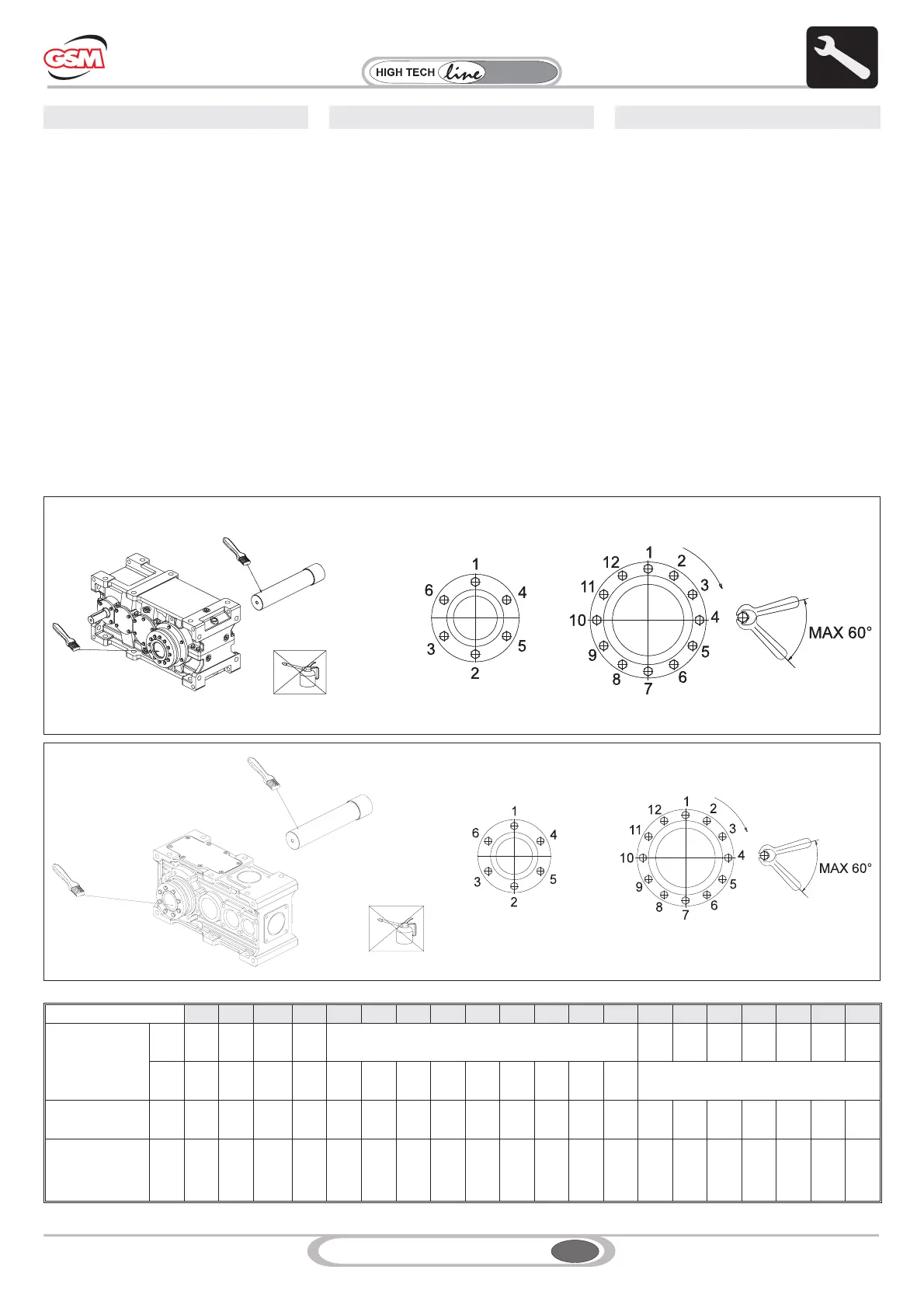
6.8 MONTAGGIO - SMONTAGGIO
UNITA' DI BLOCCAGGIO
Pulire accuratamente le superfici di contatto
dell'albero e del mozzo.
Applicare sulle stesse una leggera pellicola
d'olio.
Inserire l'unità di bloccaggio all'esterno
dell'albero cavo.
Serrare le viti in modo graduale ed uniforme con
sequenza continua sino a raggiungere la coppia
di serraggio Ms indicata in tabella.
Per raggiungere la coppia di serraggio Ms
richiesta sono necessari più serraggi delle viti.
Attenzione: non usare bisolfuro di molibdeno o
altri grassi, causa di notevoli riduzioni del
coefficiente d'attrito.
In particolare è consiglato serrare le viti secondo
lo schema a croce ma qualora il numero delle viti
è superiore a 12, per facilitare le operazioni di
montaggio è consentito il serraggio sequenziale
prestando paricolare attenzione allo schema
indicato in figura
6.8 MONTAGE - AUSBAU DER
SPERREINHEIT
Die Kontaktflächen der Welle und der Nabe
sorgfältig reinigen.
Einen leichten Ölfilm auf diesen Flächen
auftragen.
Die Sperreinheit extern an der Hohlwelle
anbringen.
Die Schrauben schrittweise und gleichmäßig in
Dauersequenz anziehen, bis das
Anzugsmoment Ms, das in der Tabelle.
angegeben wird, erreicht wurde.
Für das Erreichen des erforderlichen
Anzugsmoments Ms müssen die Schrauben
mehrfach angezogen werden.
Achtung: Kein Molybdändisulfid oder andere
Fette verwenden, da dadurch der
Reibungsbeiwertes erheblich gemindert werden
würde.
Insbesondere wird empfohlen, die Schrauben
einem Kreuzschema gemäß anzuziehen.
Sollten jedoch mehr als 12 Schrauben
angezogen werden müssen, ist im Sinne einer
einfacheren Montage, auch ein sequentieller
Anzug zulässig, wobei besondere
Aufmerksamkeit auf das abgebildete Schema
6.8 ASSEMBLY - DISASSEMBLY OF
BLOCK UNIT
Carefully clean the contact surfaces of the shaft
and the hub.
Smear the same with a light film of oil.
Place the block unit outside the hollow shaft.
Gradually tighten the screws in an even way,
with a continuous sequence until reaching the
tightening torque Ms indicated in table.
Tighten screws in steps to reach the tightening
torque Ms.
Attention: do not use molybdenum disulphide
or other greases; it would cause big reductions of
friction coefficient.
It is recommended to tighten the screws in a
cross pattern, but it is allowed to tighten screws
in a sequence in case there are more than 12, to
facilitate assembly operations; in this case
special attention should be paid to the diagram in
the figure
6. INSTALLATION 6. INSTALLATION6. INSTALLAZIONE
704 708 712 716 720 802 804 806 808 810 812 814 816 818 820 822 824 826 828 830
Coppia serraggio
Tighten. torque
Anzugs-moment
[Nm]
DIN
931
10.9
4 12 12 12 - 250 490 490 490 490 840 840
DIN
931
12.9
/ / / / 35 35 35 35 71 71 121 121 300
-
Viti di serraggio
Retaining screws
Anzugs- schraube
N°
x
M…
7
x
M5
7
x
M6
8
x
M6
10
x
M6
10
x
M8
7
x
M8
10
x
M8
12
x
M8
12
x
M10
12
x
M10
10
x
M12
12
x
M12
8
x
M16
12
x
M16
12
x
M20
18
x
M20
21
x
M20
24
x
M20
22
x
M24
24
x
M24
Coppia Slittamento
Slipping torques
Rutsch- momente
T
FU
[kNm]
0.34 0.78 1.52 2.5 8.3 4.6 8.3 12.0 20.2 23.0 31.7 42.3 61.5 86.0 138 240 320 415 612 788
 Loading...